In this web page I described how I invented and prototyped a new type of focuser which I called the Dual Speed Helical Crayford Focuser or DSHC. However, the focuser I described is very complex and difficult to build for the average ATM.
In the following text I will describe a simpler version of the DSHC focuser.
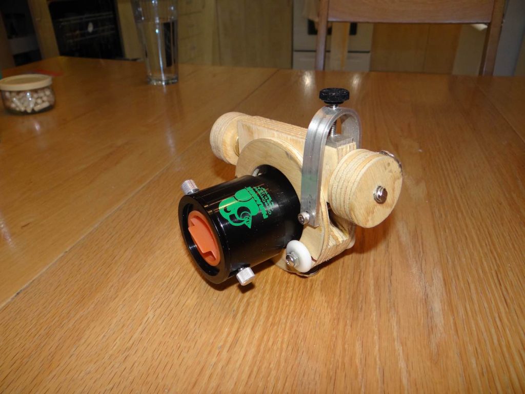
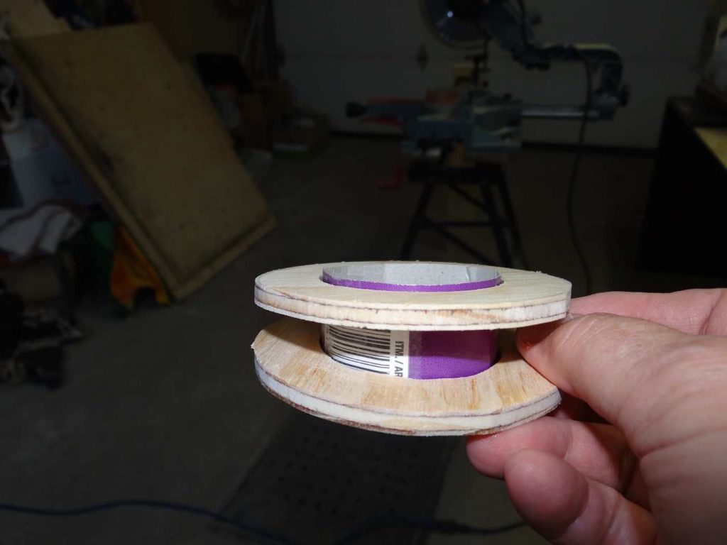
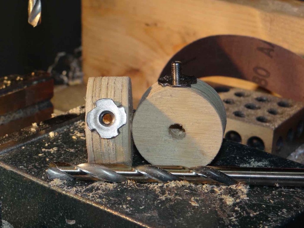
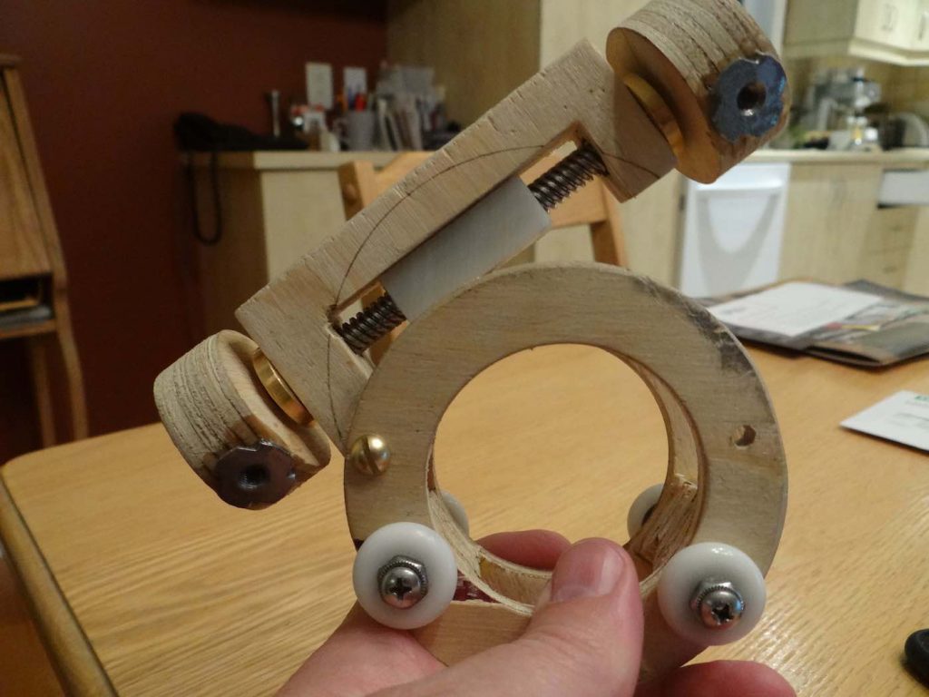
Almost entirely made of plywood, the DSHC focuser pictured above can be built for about 15$. Also it can be made in about two evenings using mostly simple tools one finds in many home shops. The most complicated machine you will need is a drill press. Otherwise a simple electric drill and an electric jigsaw is really all you need to make most of it. The level of skill to make it is not high but, you have to work with some care, as you would any fine wood project you want to look nice and work well. However, even if things are not absolutely perfect, the result will likely work anyway.
This version of the DSHC focuser assumes you are using a coma corrector like the Televue Paracorr or some of the other ones on the market. If you are going to want to have a draw tube in which you insert eyepieces directly, you will need to have that draw tube made by a machine shop. But because all the contact points with the draw tube are plastic, the draw tube does not have to be anodized or hard anodized, almost a must for any Crayford type focuser using steel ball bearings to prevent marring of the draw tube’s surface.
The 2 inch focuser pictured here only weighs half a pound. One rotation of the draw tube creates a .44 inch linear movement and one rotation of the fine focusing knob, .022 inches. This represents a 1:20 rough to fine focus ratio. The focuser can hold up to 4 pounds of vertical weight.
Making the Focuser Body
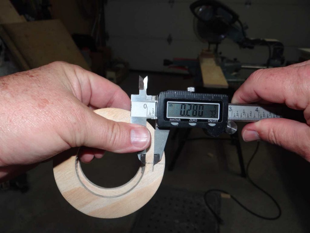
Let me begin the step-by-step construction details of this focuser with the focuser body. At 1.25 inches thick the entire focuser body is fairly thin. The ball bearings each add about another 1/4 inch on either side for a total height of 1.75 inches. That was kind of my upper limit because the 2 inch TV Paracorr has a barrel length of 3 inches, leaving about 1.25 inches of total focusing range, which will accommodate most eyepieces.
As you will see, making this focuser body is extremely easy. You will need a small sheet of 1/4 inch thick plywood. About 1 square foot is ample. You need enough real estate to hold the sheet while you are cutting the components out of it. You will also need two small bits of 3/4 inch thick plywood which will be used to space the two discs apart to provide a frame in which to mount the fine focus bracket, also made of 3/4 inch thick plywood (more on this later).
So let’s begin.
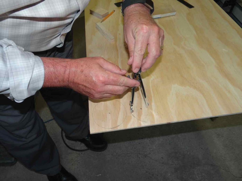
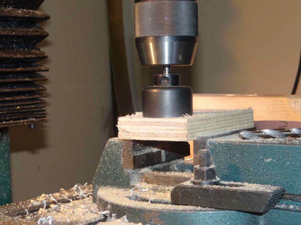
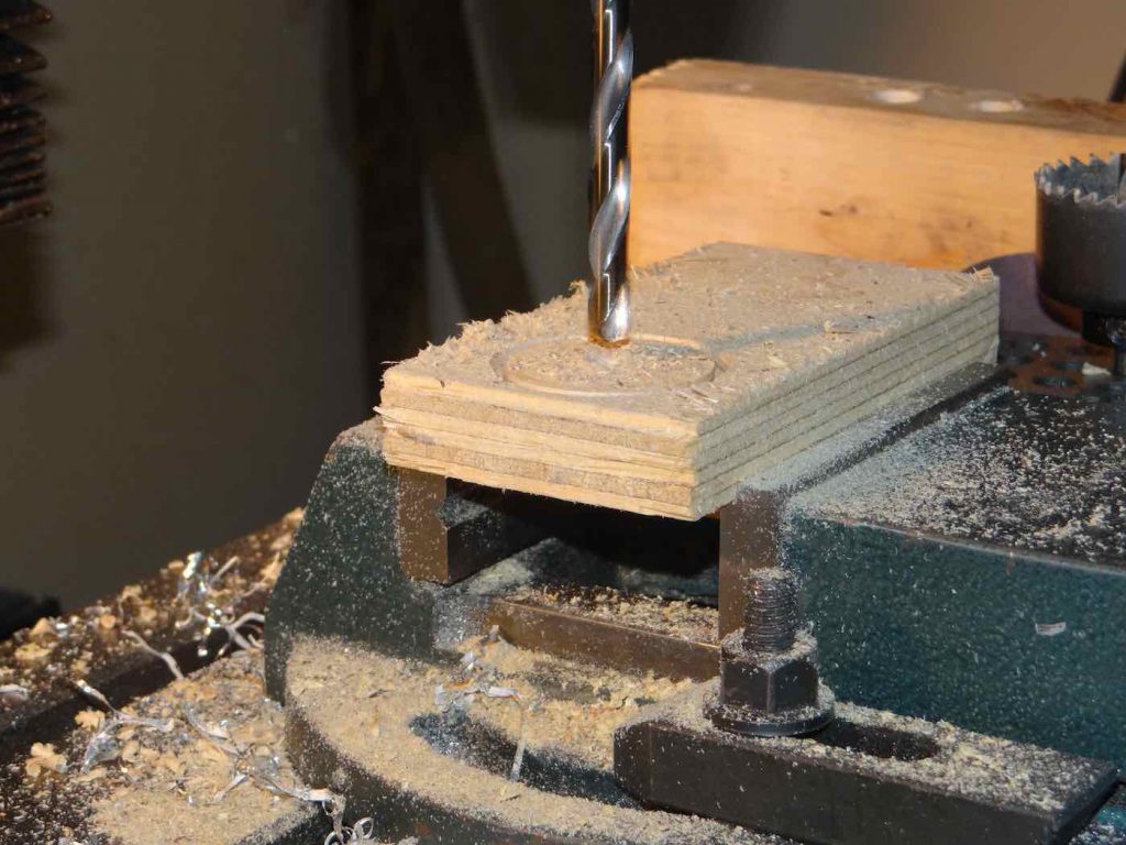
First, lay the 1/4 inch plywood sheet on a table and, using a drawing compass, draw two circles having a diameter of about 3 5/8 inches. When you’ve finished drawing the circles, drill a small pilot hole at the compass center to guide a hole saw.
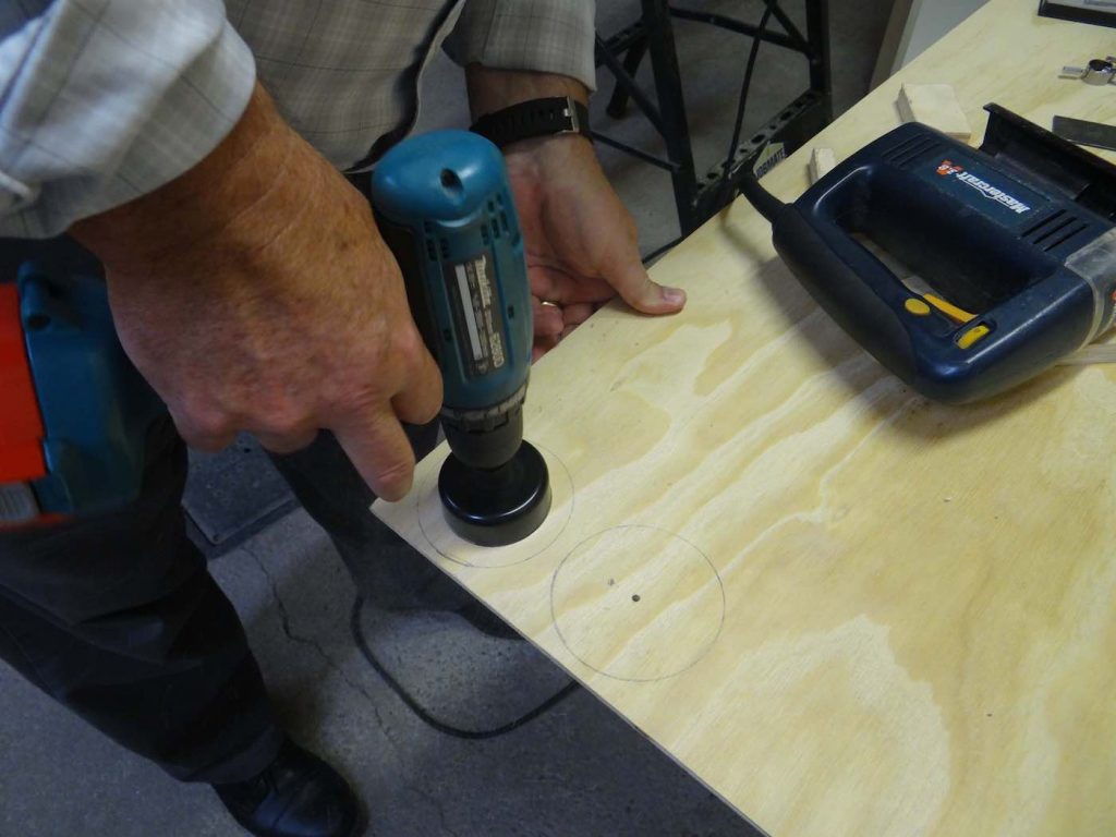
Next, drill two holes with a 2.25 inch diameter hole saw.
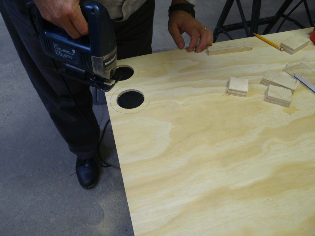
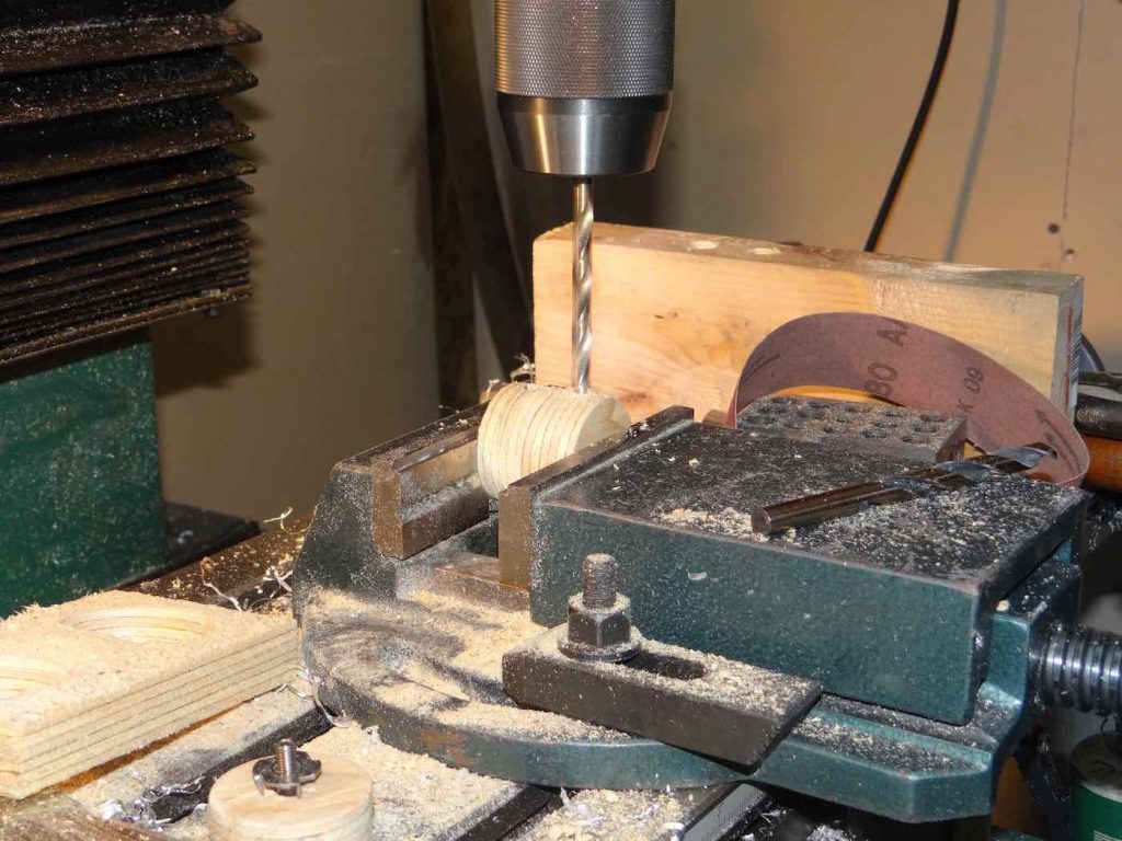
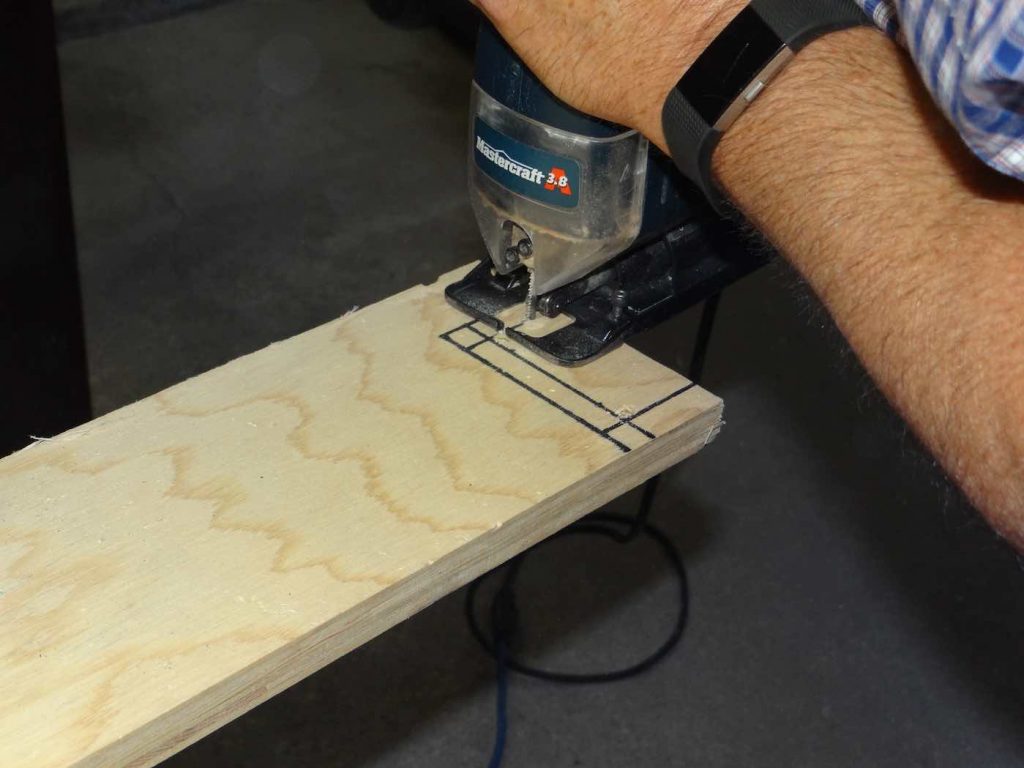
Using an electric jig saw (or a router if you have one) cut out the outer disc diameter, following along the circumference of the line you drew earlier.
The next step will be to unite those two discs with 3/4 inch of space between them. Prepare two, 1/2 inch wide x 1 inch long x 3/4 inch thick plywood spacers. To do a cleaner job, it’s best to center the two plywood discs before gluing them. The best way I found to do that was as follows:
Cut an 8 inch long x 1 1/8 inch wide strip of carton or thick paper. I used a cereal box lid.
Insert this strip inside the center of the two discs and tape it so it stays round.
Place one of the discs on a piece of paper and, using carpenter glue, glue the two small plywood cleats you prepared earlier to the bottom disc. The cleats should be spaced at an angle of approximately 120 degrees apart. Then, add some glue to the top of the cleats. Using your circular cardboard strip to center the two discs, pressing everything together to get the glue properly spread out.
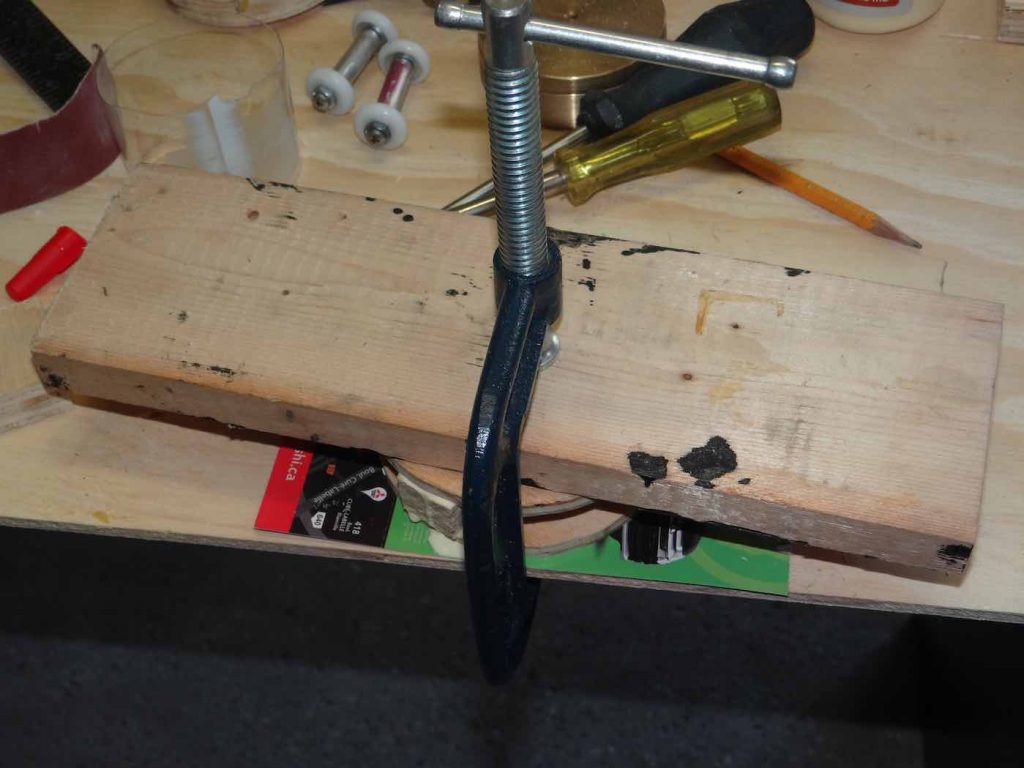
Finally use a small plank of wood on top of the top disc and tighten everything together with a small C-Clamp and let dry for a few hours.
Unless you use a circle jig to cut out the outer diameter of the discs accurately, you may find when you remove the C-Clamp that the outer circumference will be a bit rough and not always circular. Cutting a disc free hand with a hand held jig saw will do this. You can clean everything up with some sanding. I cheated and used my lathe to clean it up but that’s just because I was lazy.
Preparing Ball Bearing Shafts
The four ball bearings will first be mounted on two short shafts. These two shafts will then be inserted and glued in inclined holes in the focuser body. In this post I will show how to prepare the ball bearing shafts.
One of the challenges of making a Helical Crayford focuser is mounting the inclined ball bearings so that their angle is compatible with the finesse of the focusing movement you want for your telescope. You also want to position the bearings so that their point of contact with the eyepiece draw tube is such that the draw tube is as perpendicular as possible to the focuser body. The focuser will still work even if it’s a bit crooked since you will be able to make the draw tube axis concurrent with the optical axis by adjusting the focuser position with the three attachment screws (more on these later). But the focuser will look a lot nicer if you work carefully and center the bearings as accurately as possible.
So, restraining myself from using my lathe, I devised the following method using only hand tools and a drill press:
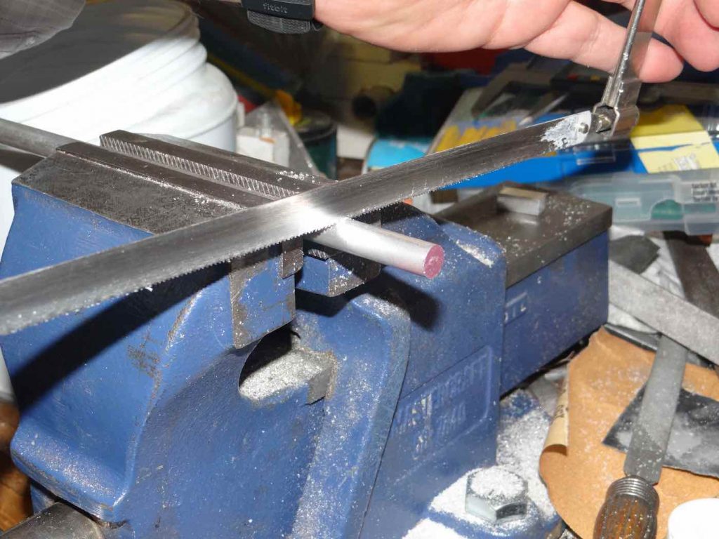
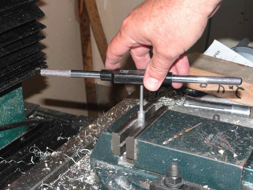
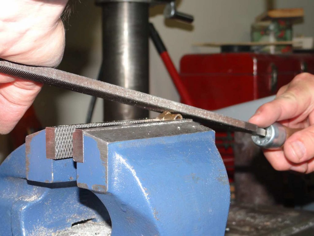
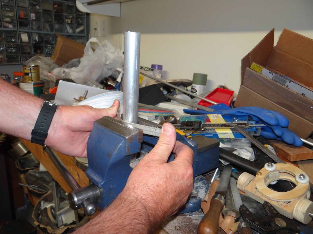
You will first need a small length of 3/8 inch diameter aluminium shaft. You can find these at your local hardware store. Mount it in a vise and cut two pieces having a length of between 1 3/8 and 1.5 inches. I don’t know about you but whenever I cut something in the vise with a metal hacksaw, it’s never perfectly perpendicular. We want both ends of the shaft to be perpendicular in order for the two bearings to be rotating in the same plane.
Here’s the method I came up with to square the ends of the shaft:
Place the 3/8 inch shaft in the chuck of a drill press. Make sure the drill press table is as perpendicular as possible to the spindle shaft. Adjust as necessary. Place a fairly coarse file flat on the drill table or in the vise. Start the drill press, bring the end of the rotating shaft in contact with the file and wear out the shaft end until it is square. Repeat with the other side of the shaft. Neat isn’t it!
By the way the two shafts don’t need to be exactly the same length. What is necessary is that they be long enough so that they stick out of the focuser body enough to attach the ball bearings, without the bearings touching the focuser body.
With the shafts now nice and square, we need to drill perfectly centered holes for the bearing shafts. Again, restraining myself to simple tools, here’s how I did it:
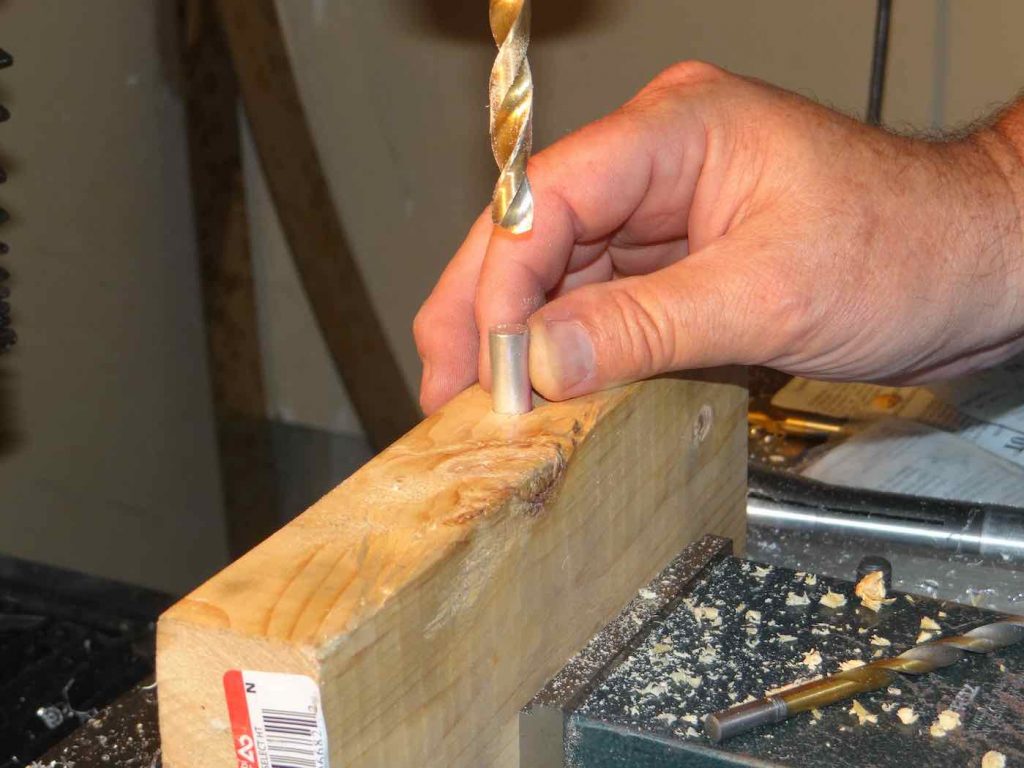
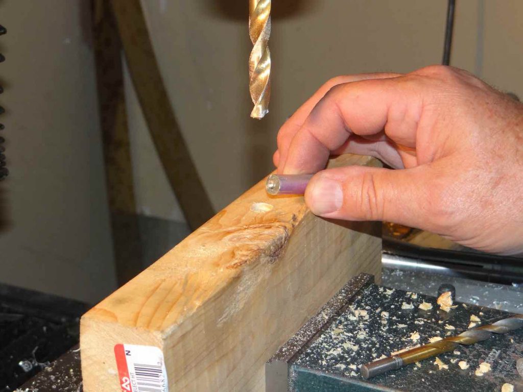
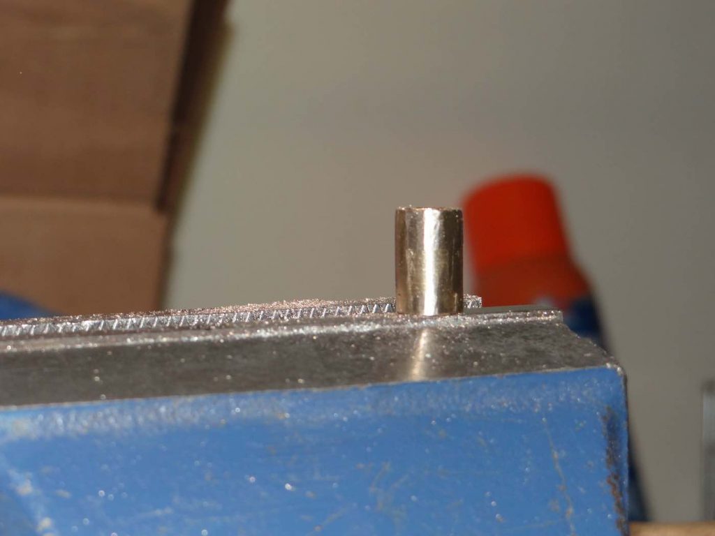
Take a short piece of 2 x 4 wood piece. Using a 3/8 inch diameter drill bit, drill a deep hole in the wood. The hole should be at least 2 inches deep. Without disturbing the piece of wood, drill another, smaller hole concentric to the first one which will go all the way through the piece of wood. I drilled a 1/4 inch hole, leaving a ridge inside to hold the aluminium shaft. Insert a shaft in the deep hole and with the drill press and the 3/8 inch diameter drill bit guided by the top of the hole, mark a small crater with the tip of the 3/8 inch drill bit on the surface of the shaft. Remove the shaft (insert a nail through the back of the 1/4 inch hole to push shaft out if it’s stuck) and repeat on the other side. Do the same with the second shaft.
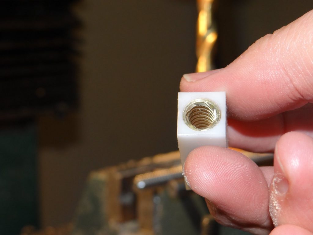
What you will end up with looks like this. Notice the small crater in the center. It will serve as a guide for the drill bit:
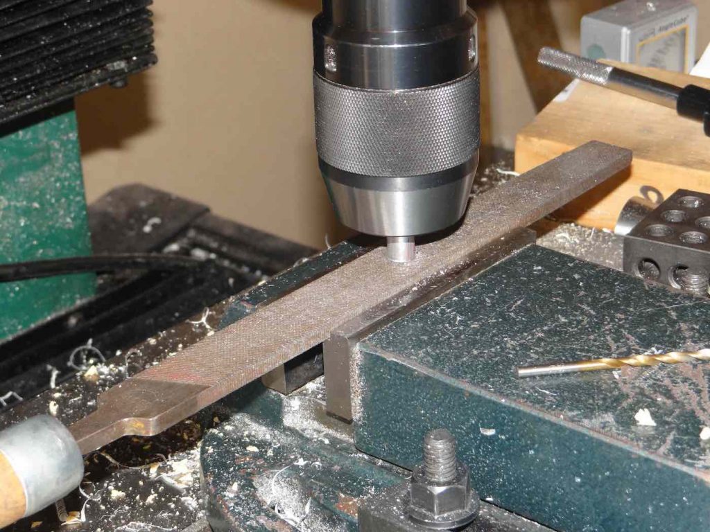
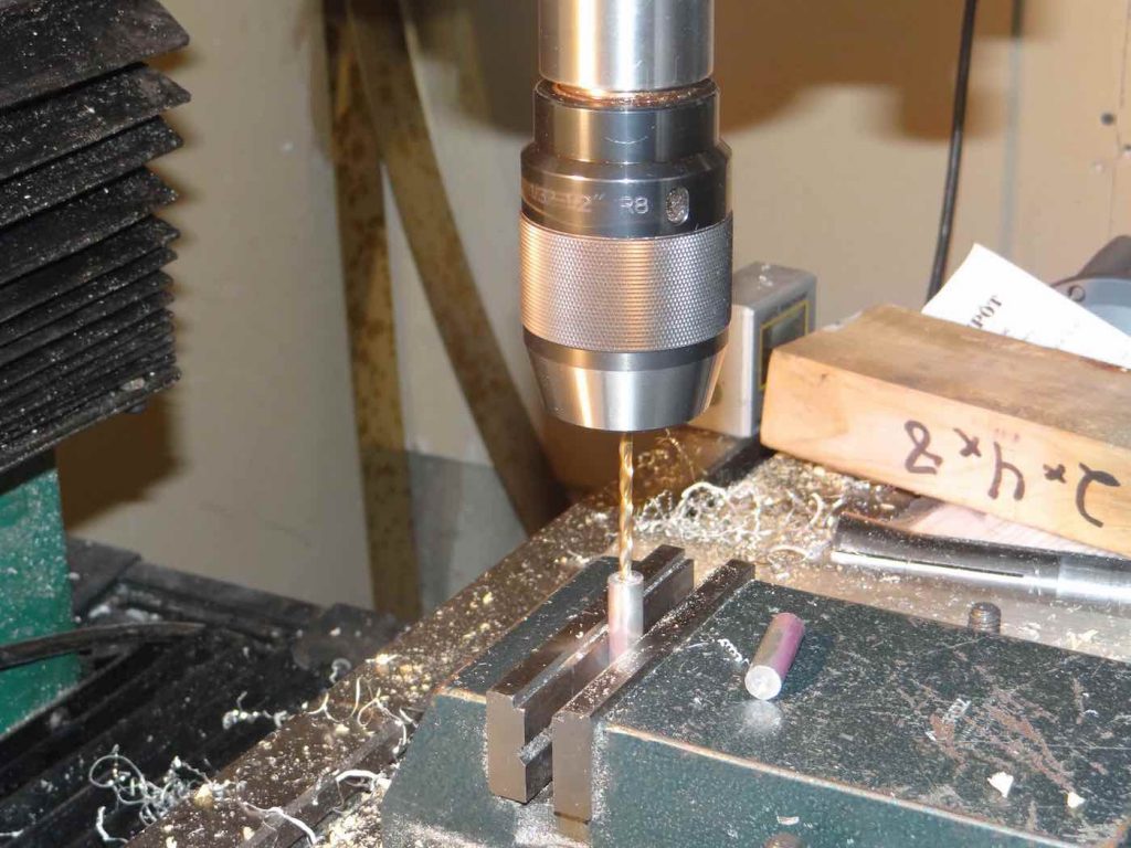
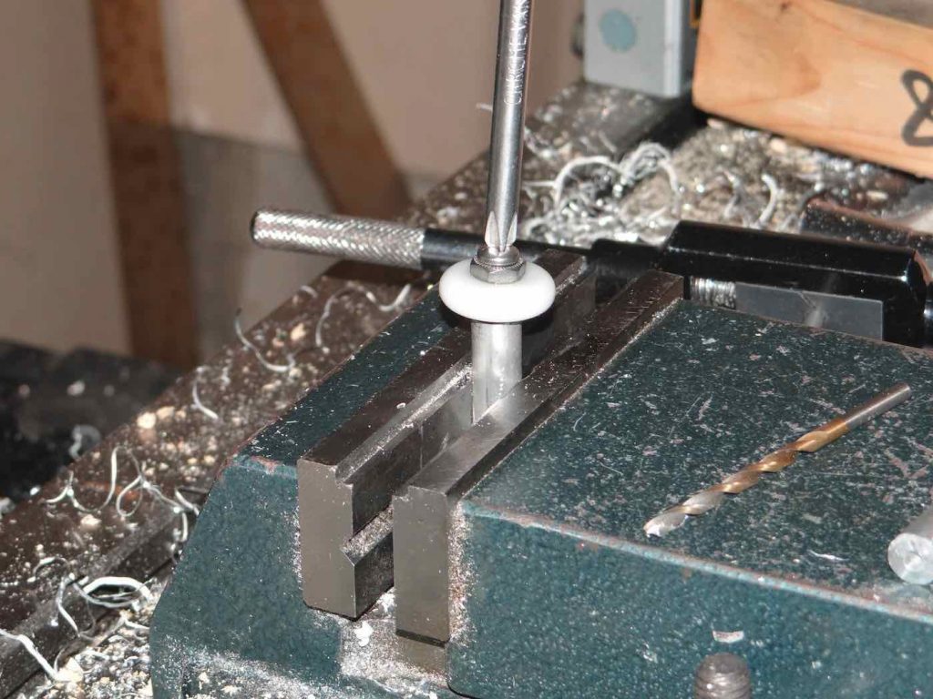
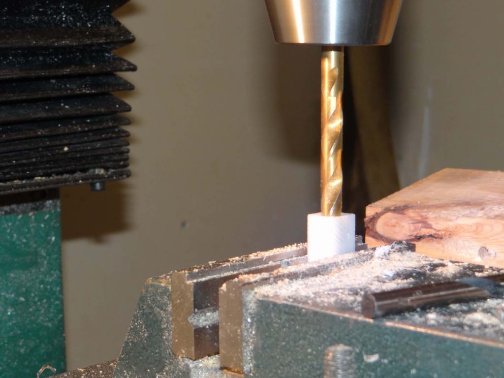
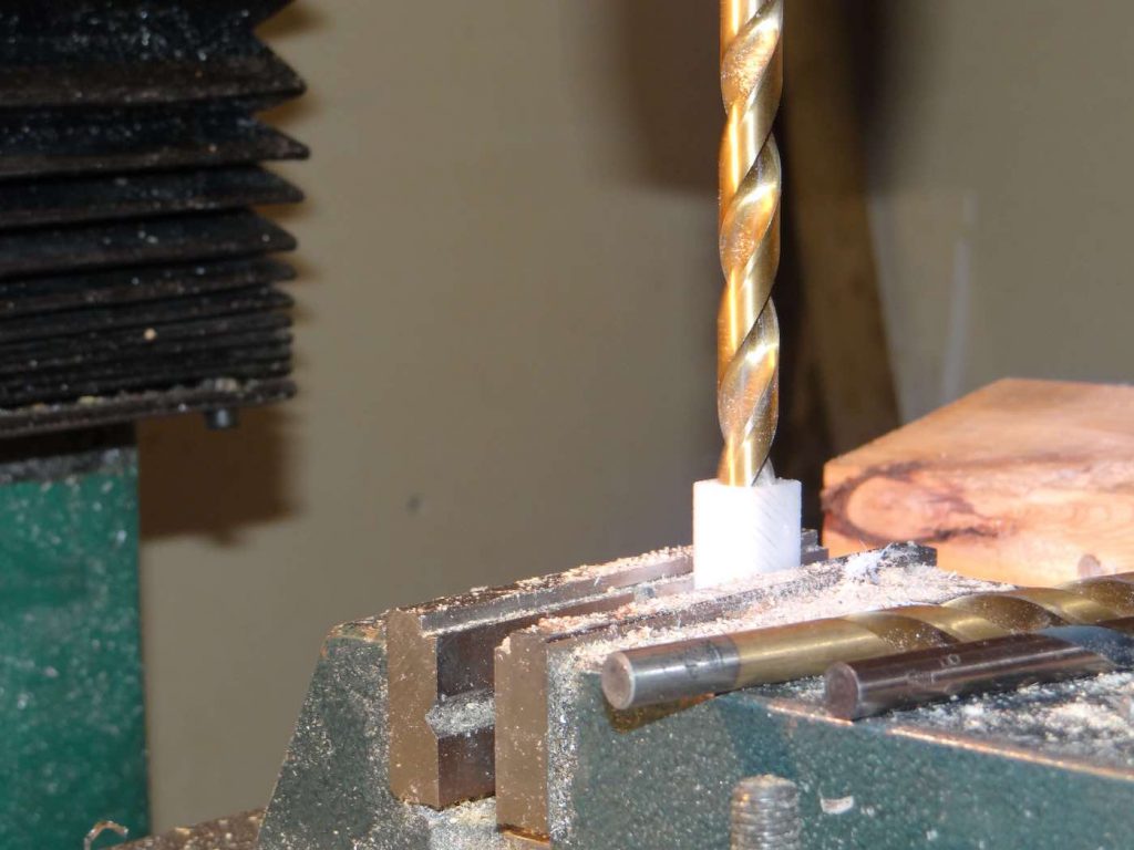
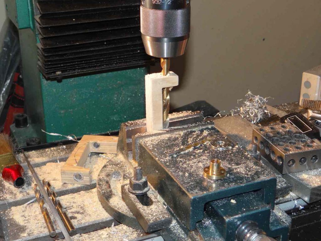
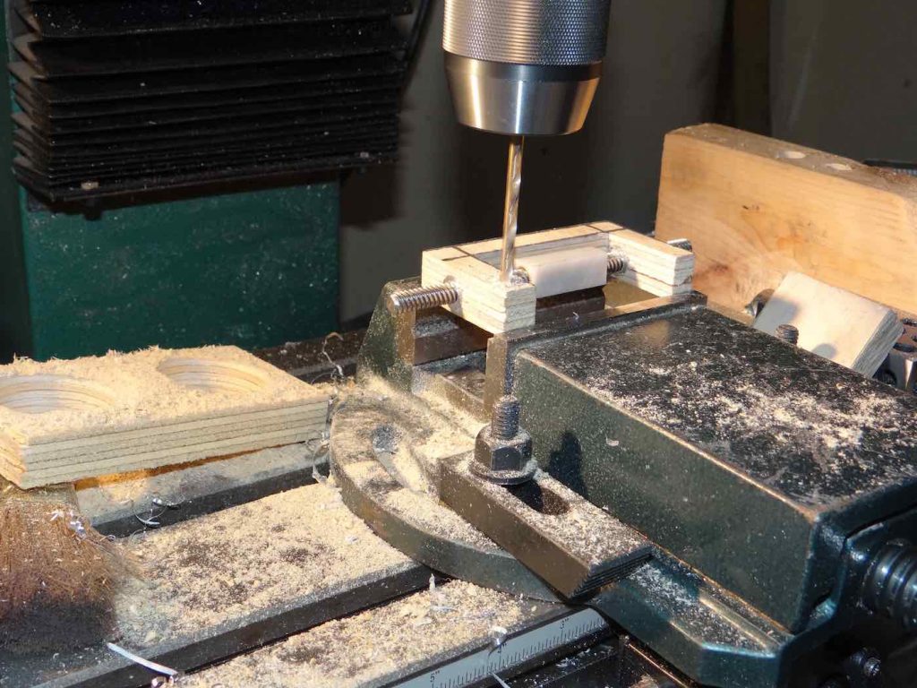
You are now ready to drill a perfectly centered hole in both ends of the shaft. Although the shafts are only about 1.3 to 1.4 inches long, I recommend drilling from both ends to prevent the drill bit from wandering inside the shaft and exiting the other side of the shaft no longer centered. So you drill the first hole about half way through, turn around and drill from the other side until both holes meet in the center.
The drill size here will depend on the bearings you will be using. In my next post I will show you the bearings I used. These require an 8-32 fine thread bolt so I drilled with a #29 drill bit and tapped the hole accordingly.
The drilling operation should be done in a vise:
Assembling the Ball Bearing Shafts
With the shafts now made, the ball bearings can be mounted on them.
I looked around various hardware stores to locate ball bearings that could be used for this simple, wooden focuser and found these:
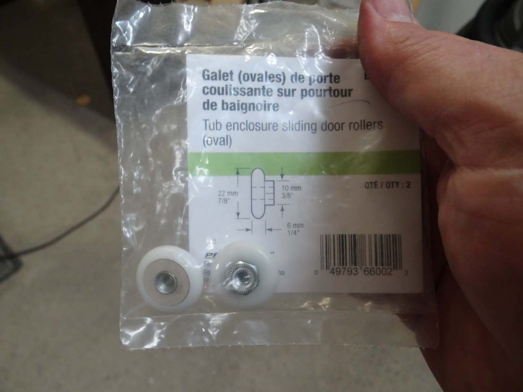
They are 7/8 inch diameter replacement ball bearings used on glass shower doors. Thus, they are designed to not rust, which is a good thing since a focuser is exposed to dew. They cost about 1$ each. I looked on Ebay and found similar bearings in various diameters, so they are very common. Note that these bearings are far from the quality of the acetal bearing I used to assemble the 3 inch focusers and it shows in the backlash I measure when I reverse fine focus direction. In the 3 inch focusers the backlash was about 0.000 7 inch which is quite acceptable. With these cheap bearings its more like a few thousand of an inch. Kind of what you find with the old rack and pinion focusers we used on telescopes in the ’70’s and ’80’s. Still functional but not ideal for f/5 and faster scopes due to the shallow depth of field.
I’m still experimenting with these. Of course if you can purchase acetal bearings, which cost about 7$ each (they are available on Ebay or, if you have access, at McMaster Carr), you will get a tighter focusing effect. You could also use stainless steel bearings like those used for roller skates. They can be pretty inexpensive. The reason I recommend plastic bearings is to prevent scratching the expensive coma corrector.
As mentioned above, the central bolt on the bearings I purchased are 8-32 threads. Consequently, I used a tap that fit those threads and tapped both ends of each shaft:
With the shaft in the vise, I then screwed on the ball bearings:
I found the bolt that comes with the ball bearings was too short for my application so I had to purchase slightly longer ones.
This is what the two ball bearing units look like after final assembly:
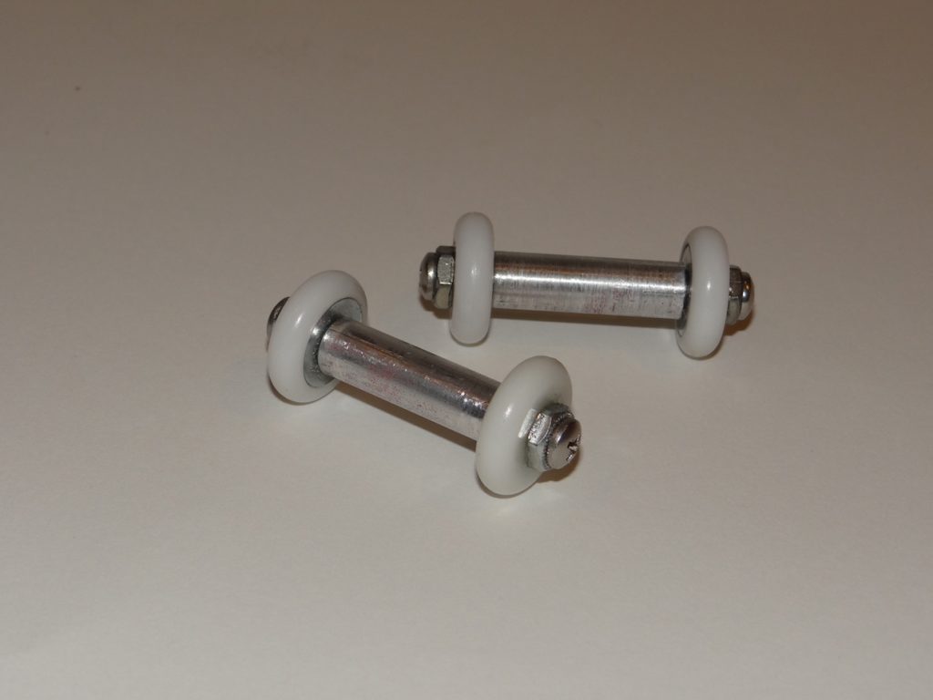
So we now have a focuser body and ball bearing units. Next step will be to assemble these three parts together.
Assembling the Bearings to the Focuser Body
Now that we have a focuser body and a pair of shafts mounted with ball bearings, we can proceed with assembling them together into a finished focuser body assembly.
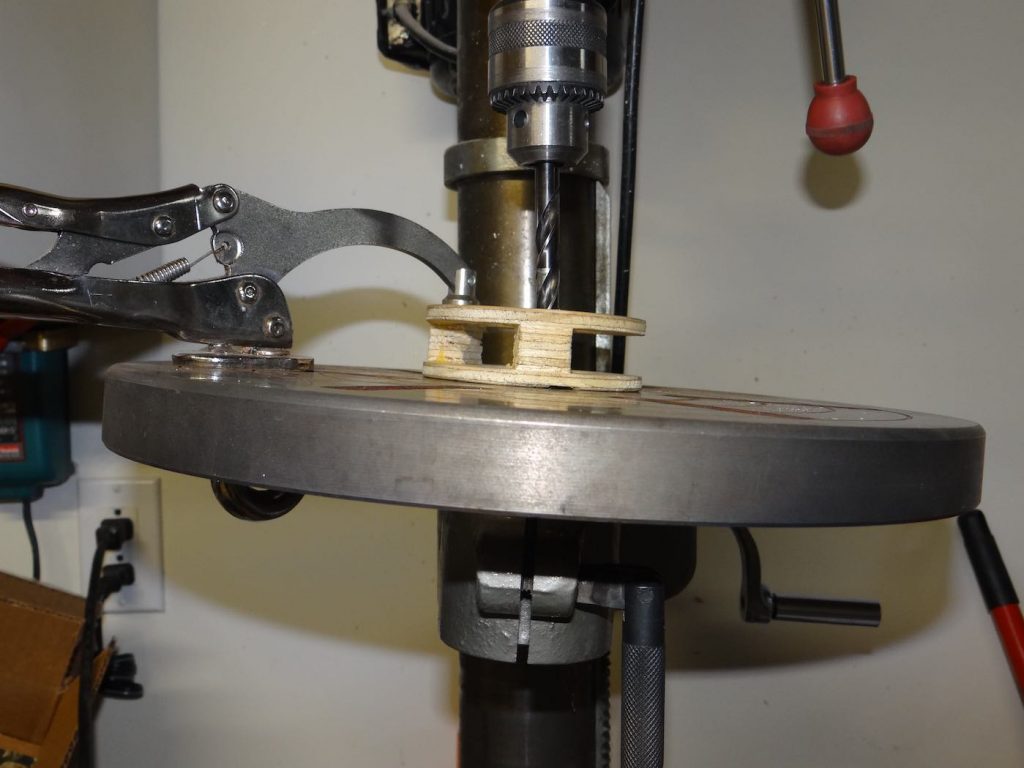
The first step is adjusting the drill press table to the angle you want for your bearings. For a 2 inch DSHC focuser I recommend between 5 and 6 degrees of angle. This bearing angle will produce a linear movement of the draw tube of about half an inch per draw tube rotation. This is a good speed for the rough focus adjustment knowing that the fine focus adjustment will be about 1/20th of that. A good compromise.
So, with a drill press having an adjustable table, incline the table to about 5 to 6 degrees. If you don’t have an inclinometer like a Wixey or other adjustable level, you can use an iPhone which comes bundled with a level measuring app:
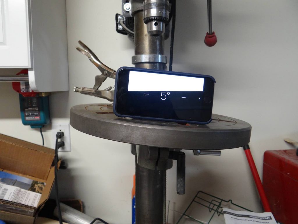
Once the angle is adjusted, lock the table.
Next you must determine where you will drill the two holes for the bearing shafts. To determine this you must first measure as accurately as possible the inside diameter of the focuser body that you obtained when you drilled out the hole with the hole saw. Knowing the draw tube diameter (in this case the draw tube is the Paracorr which has a diameter of 2 inches) and the diameter of your bearings, you simply subtract the radius of the focuser body hole from the radius of the Paracorr. This will give you the gap between the two. For example I measured an ID of 2.29 inches – 2 inches for the Paracorr = 0.29. Divided by 2, this gives an annular gap of about 0.15 inch.
The bearing diameter I’m using for this demonstration are 0.858 inches in diameter, or about 0.43 inch radius. Substracting the gap from the radius of the bearing determines how far from the edge one must drill the holes: 0.43 – 0.15 = 0.28 inches:
Before drilling the 3/8 inch diameter holes (diameter of the aluminium shaft), I first drilled a small pilot hole to make sure I was at the location I had marked with the vernier. I then proceeded to drill the two holes:
Some details about drilling these two holes:
- It’s preferable to make sure the holes are being drilled as tangentially as possible to the focuser body. If not the two bearings will not make contact with the draw tube in the same plane and the draw tube will be inclined a bit in relation to the focuser body. However, if there is some angle, you can compensate when you mount the focuser on the tube to match the optical axis. It just looks nicer when things are square on.
- The holes will be drilled 120 degree apart, through the two cleats that separate the two thin plywood rings. When you align the position where you will start drilling, move it a bit to the left of the center of the cleat so that when the hole emerges on the other side it will be a bit to the right of the center of the cleat. If you start in the center of the cleat you are not benefiting from the strength and full width of the cleat since the hole will emerge near the bottom edge. Again, it will probably work well anyway (my focuser design is very forgiving) but why not try to balance the hole position to have a better symmetry.
- Notice I inclined the table in a clockwise rotation. I prefer this because the resulting focusing movement will be like the movement of the right hand screws we are used to working with: i.e. holding a bolt in your hands, if you rotate clockwise the nut moves away from you and if you turn counter clockwise, it will move towards you. Same should happen for the focuser tube. My brain would have a lot of trouble adjusting to the fact that turning the draw tube clockwise would move the eyepiece outside of focus.
After you have drilled and cleaned up the holes you should dry mount the bearings and try your draw tube before going further. If the gap between the draw tube and the focuser body is not to your liking (not centered enough), you can always make another focuser body and try again, learning from the first one. It only takes 30 minutes to make another focuser body. I don’t recommend gluing the shafts to the focuser body until the end. On mine the shafts are quite tight in their holes and I don’t plan on gluing them at all.
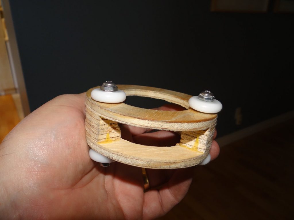
Here is what the assembled focuser body looks like:
An Option: Making a Helical Crayford Focuser instead
At this point allow me to introduce an easier to make focuser option many might prefer to the more complex DSHC focuser. Indeed, once you have the ball bearing shaft assemblies made, you could very easily make a more ubiquitous Helical Crayford focuser and call it done:
For this focuser I used the exact same technique described earlier to make the two 1/4 inch thick rings of the DSHC focuser assembly, but with thicker 3/4 inch plywood instead. It took me less than 15 minutes to make this focuser since I already had the bearing shaft assemblies. For the pressure screw I used a 1/4 inch nylon bolt which you can find at hardware stores. I tapped the 1/4 inch tread directly through the plywood but would recommend gluing a threaded insert, which you can purchase at hardware stores.
If you assemble one of these single speed HC focusers, I recommend scaling back the bearing angle to between 2 and 3 degrees. At 2.5 degrees I measured a linear motion of 0.2 inches per rotation of the 2 inch Paracorr. It’s a reasonable compromise between speed and accuracy of focusing for f/5 to f/8 instruments.
The Fine Focus Bracket Assembly
The fine focus bracket assembly is what transforms the conventional Helical Crayford focuser into a dual speed, fine focuser one.
Here is what it looks like:
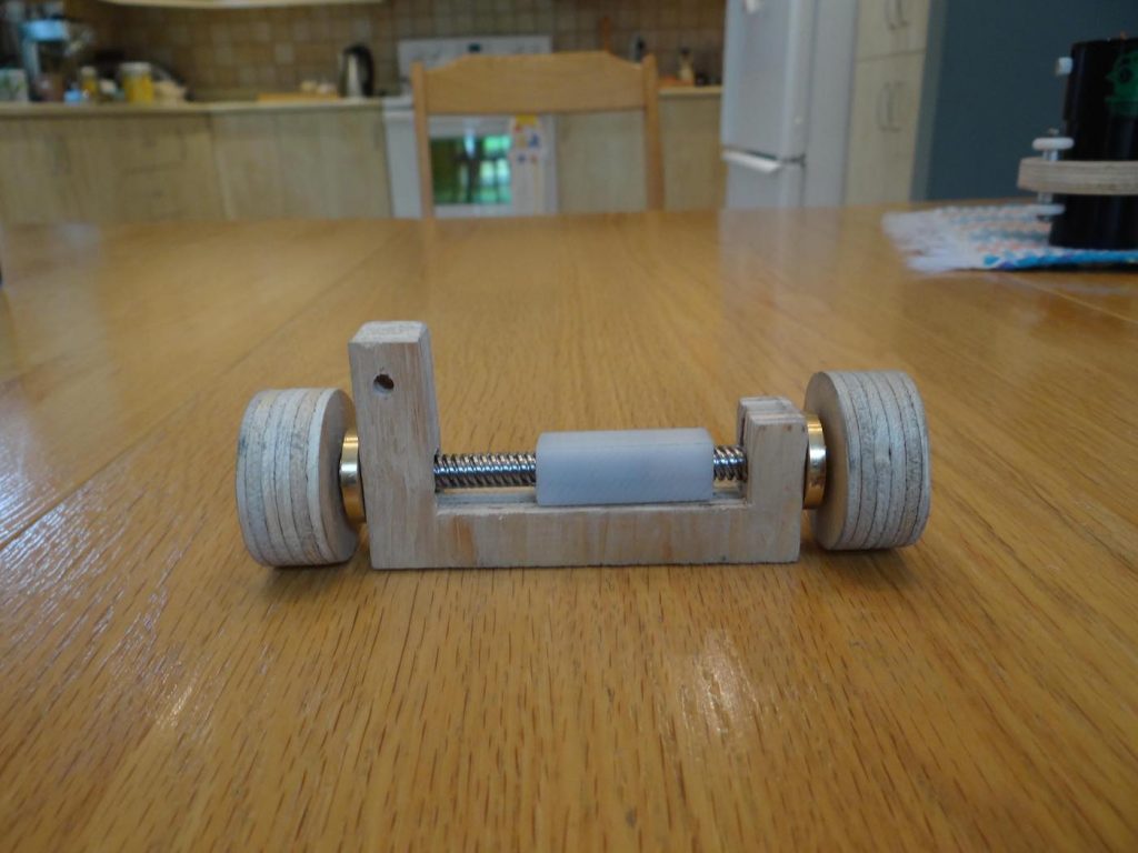
The main body is made of 3/4 inch thick plywood which supports the fine focus lead screw and fine focus slide, along with brass bushings and plywood focusing knobs. The tricky parts of this fine focus assembly have to do with the lead screw, brass nut and brass bushings. But the nice thing is that you can purchase these critical parts on Ebay. Everything else can pretty much be made and assembled in about an hour using ordinary tools + a drill press.
Preparing the Bushings
Before we assemble the fine focus bracket assembly, we must firs prepare the individual parts that make it up. Let’s begin with the brass bushings. If you have access to McMaster Carr, I’ve found these flanged 8mm ID x 12mm long Oilite bushings perfect for this application. However most people cannot purchase from McMaster. On the other hand you might be able to find the right size bushings on Ebay.
The easiest way I’ve found of making the lead screw bushings is to modify brass threaded nuts that normally come with the lead screws and drilling out the threads. When you purchase the lead screw and its brass nut, buy it from a location that also sells the brass nuts by themselves. Here is the vendor from which I purchased my lead screws. He sells sets of lead screws with one nut, but also sells individual nuts without lead screws. You want to purchase 8mm diameter x 150mm (6 inch) long screws with a pitch of 8mm. The extra nuts can have any thread (you will be drilling them out) but may as well buy 8mm pitch ones. As a precaution I recommend purchasing at least three extra nuts (rather than just two) in case something goes wrong when drilling out the threads. The delivery times from these Chinese suppliers can be very long and the nuts are pretty inexpensive (about 2$ each) so may as well purchase one or two more while you are at it.
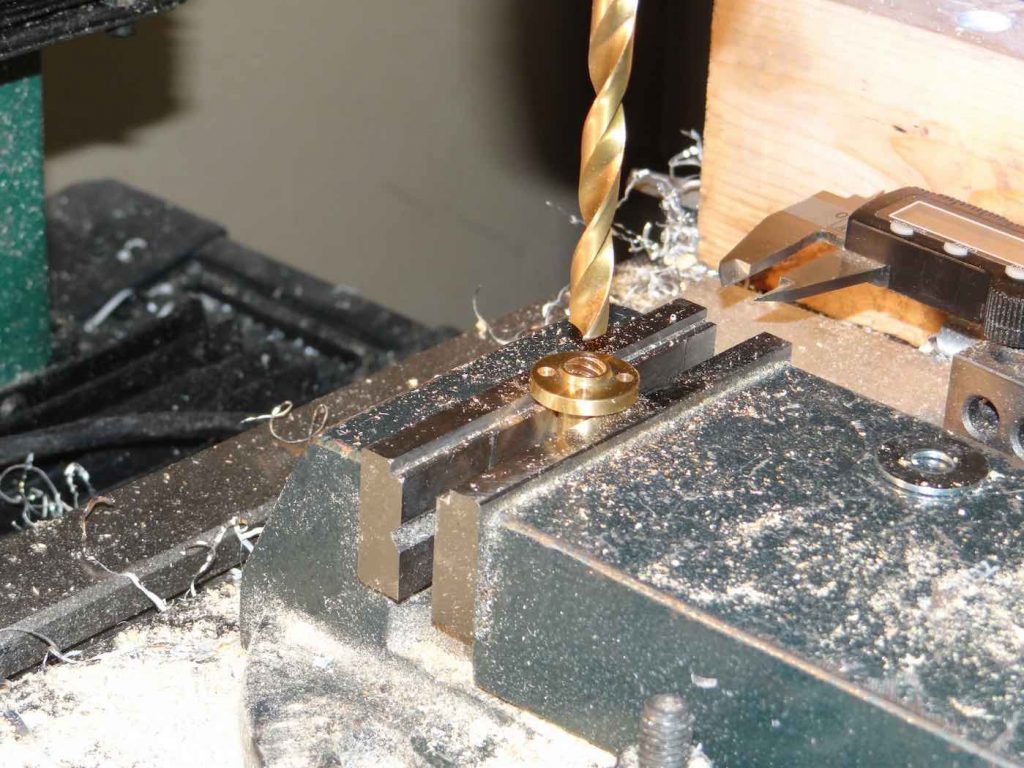
This picture shows how easy it is to drill out the thread. You simply hold a bushing in a vise and, using a 21/64 inch diameter drill bit, drill through the threads. This will remove most of the thread, down to a diameter of about 0.326 inch. The 8mm lead screw having an outside diameter of about 0.316 inch, leaves enough looseness to accommodate any significant misalignment of the two bushings. Although this is a very simple operation, one word of caution: don’t over-tighten the vise when holding the nuts for the drill through. The walls of the bushing will become fairly thin when you’ve drilled out the threads. You could end up permanently deforming the bushing out of round, creating an oval hole. This would create binding of the lead screw when you are fine focusing.
Preparing the Threaded Nut
Next step is preparing the threaded nut which is imbeded inside the plastic fine focus slide. The main goal here is to remove the flange the threaded nut comes with so it can be inserted in a small hole in the slide. With a lathe it’s easy: just insert it in a three jaw chuck and cut. But my goal was to find a way of doing it with simple tools.
First step is to place the threaded nut in a vise and cut away as much of the flange as possible with a hacksaw. Again, a word of warning: don’t over tighten the nut in the vise or you will deform it (the reason I keep coming back with this is because I made that mistake with the first ones).
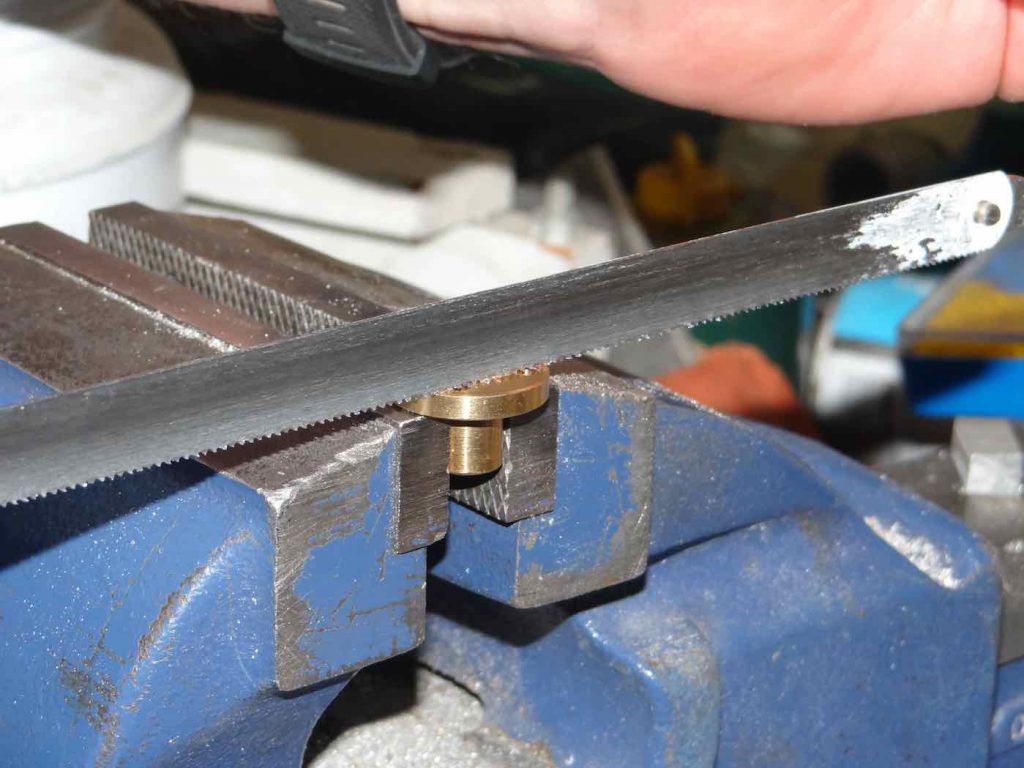
After you have cut four sides you will end up with something that looks like this:
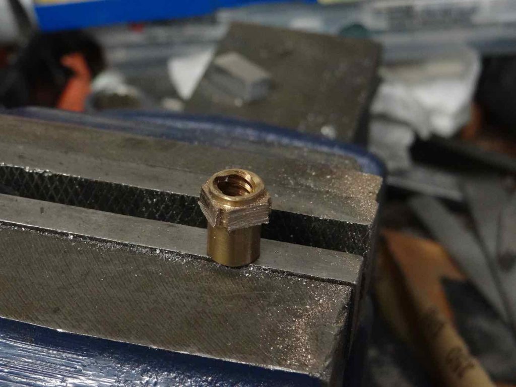
You then again place the nut in the vise and, with a file, file away the excess material until you get to the base diameter, like this:
This will require filing a bit, rotating in the vise, filing again and so on. Not the most exciting thing to do but after a few minutes you will end up with a more or less round nut, ready for a tight insertion in the plastic slide. Here is what the final result should look like:
Fine Focus Slide Assembly
Once the threaded nut is ready, making the fine focus slide assembly is pretty straightforward but, there are two small obstacles that must be overcome. The first one is: where to find the plastic sliding rectangle? Again, if you have access to McMaster Carr it’s easy. You can order this. If not, I found this on Ebay which I think would do the job. All you need to do is cut a 1/2 inch wide slice. You could also use this, which is a little thicker making drilling the hole in the center easier. A third option which I have not tried but which should work is to use a cutting board with the appropriate thickness and cut a small slice. You will need a board with at least 1/2 inch thickness. These are not as easy to find as it sounds. I had to do several stores but finally found one in a store specialized in kitchen accessories. It was not quite 1/2 inch thick, more like 0.470 inch but, with careful alignement in the drill press, drilling should be possible. Most Wallmart type stores only carry the thinner boards.
Once a rectangle of 1/2 x 1/2 x 1 1/2 inch long plastic material is at hand, align it in the vise as accurately as possible. One way of ensuring you are drilling in the center is to wrap a piece of paper around the rectangle and lower a 1/2 inch diameter drill bit, adjusting the position of the plastic rectangle until the drill bit is centered.
You then proceed to drill a first hole with the same 21/64 inch drill bit used to drill out the threads for the bushings:
You then replace with a 13/32 inch diameter drill bit and drill a larger hole over a depth of about 1/2 to 5/8 inch for the threaded nut to nest in:
The final result should look like this and the nut should have to be forced in by squeezing in a vise:
The Focusing Knobs
The next components in this fine focus bracket assembly are the two focusing knobs. For simplicity sake I decided to simply try making these out of 3/4 inch thick plywood. These are very easy to make.
The knobs themselves are simply cut using a 1.75 inch diameter hole saw. You could also make them a little bigger or smaller in diameter, depending on the hole saw you have in your shop, but I found that using a 1.75 inch diameter hole saw produced a 1.5 inch diameter knob which fits well in the hands.
You simply cut a small piece of 2.5 x 5 x 3/4 inch thick plywood. You fix it in a vise or clamp it on a sacrificial 2×4 on the drill press table and cut two holes:
Start drilling until the hole saw drill has cut about 1/4 inch into the plywood and stop the drill press. Replace the hole saw with either an 8mm drill bit if you have one or the 21/64 inch drill bit used previously:
The 8mm bit is better because it makes a nice tight hole around the lead screw and there is less wobble when you rotate the fine focusing knob but a 21/64 inch drill bit will also work, albeit with a small amount of wobble.
Once you have drilled the hole for the lead screw all the way through the knob, put the hole saw back in the drill press chuck and finish cutting out your focusing knob. Repeat for the second knob.
Next, you will need to put a set screw in each knob to firmly hold it onto the lead screw shaft. What I did here is I purchased two 8-32 threaded inserts and drilled 1/4 inch holes in the side of each knob to drop the inserts in (you could use other sizes of threaded inserts, as long as they can be impeded in the plywood focuser knobs):
Once I was sure the threaded inserts fitted correctly in their orifices, I prepared some epoxy glue which I generously applied in the hole and on the threaded insert flange to glue the inserts to the sides of the knobs. This is what it looked like before the glue was applied:
I waited 24 hours before applying any pressure with the set screws. If you don’t wait long enough the glue bond will not be able to overcome the high pressures generated by tightening the screw against the lead screw and the insert will slide out of its hole. I found that after 24 hours, the glue had completely cured and the bond was rock solid.
I happened to have stainless steel setscrews available but you could use any screw for this purpose.
I haven’t done so yet but you could cover the sides of the knobs with heat shrink tubing to increase the grip. You could also use another kind of insert that does not protrude beyond the periphery of the knob. It would look nicer. Use your imagination and whatever components you have available.
Making the Fine Focus Bracket
The only part missing to assemble the fine focus bracket assembly is the bracket body which holds everything together. This part is made of 3/4 inch thick plywood. To begin, here is a sketch of the fine focus bracket assembly that I made for this project:
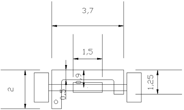
The bracket is about 3.7 inches wide (about the width of the OD of the focuser body). One side of the U shaped bracket is 2 inches long and the other side about 1.25 inches long. We will see why it is necessary the sides be different in one of the next posts.
The hole centers for the bushings are located about 0.9 inches below the top of the bracket. The plywood bracket is about 1/2 inch thick both on the top and on the sides.
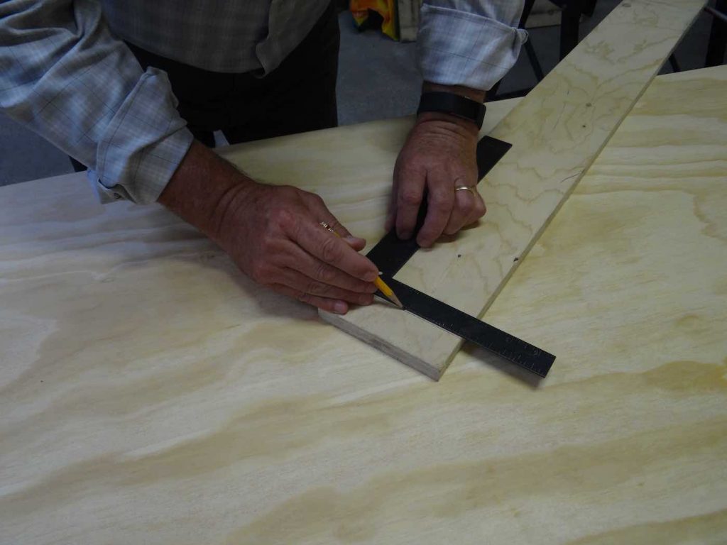
To make the wooden U shaped bracket you first draw the outline on a piece of 3/4 inch thick plywood:
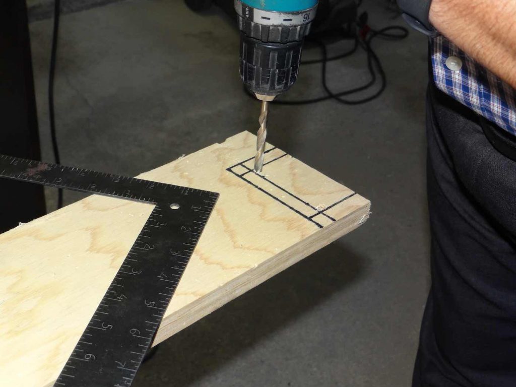
Next, two 1/4 inch holes are drilled in the inside corners of the bracket to allow a 90 degree rotation of the jigsaw when getting to those corners:
Then the shape of the bracket is cut with a jigsaw:
Finally the holes for the bushings are drilled. Try to align things as squarely as possible to prevent the bushings from being misaligned, which would create binding when operating the fine focus knob. I used a 13/32 inch drill bit for this and drilled all the way through both ends to make sure the two holes were aligned by the drill bit:
With all the parts now made, it is easy to assemble them together in a fine focus assembly bracket which will look like this photograph I showed at the beginning of this section:
Final Assembly of Plywood DSHC Focuser
Two things need to happen to finalise the assembly of the plywood DSHC focuser:
- The fine focus bracket assembly must be attached to the focuser body
- A way of applying pressure to the fine focuser bracket, pushing against the draw tube or coma corrector must be incorporated in the focuser
Assembling the fine focuser bracket assembly to the focuser body is pretty simple. Since the body is made from 3/4 inch thick plywood just like the two cleats that separate the two 1/4 inch rings of the focuser body, the fine focuser bracket fits nice and tight in the wide “slot” opposite the two pair of bearings.
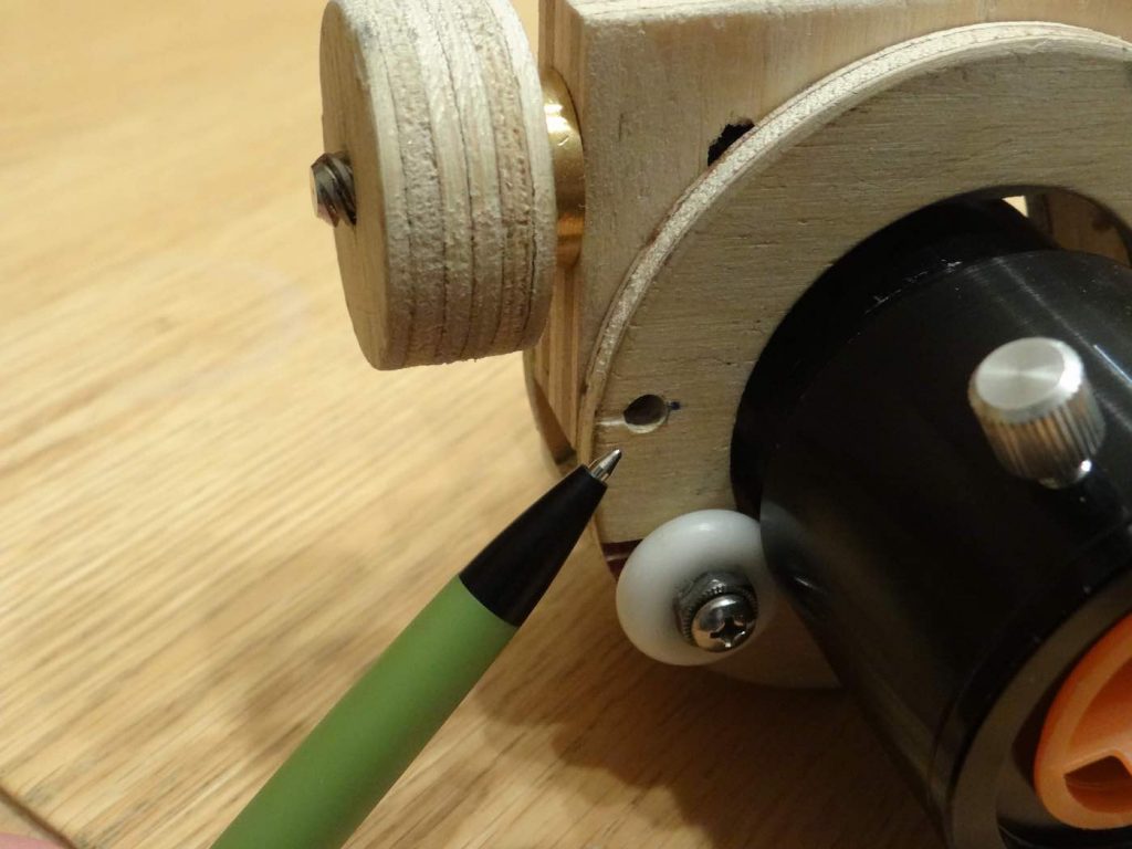
All we need to do is fit the fine focuser bracket assembly in that slot, place the draw tube or coma corrector in position and mark a spot on the focuser body where a small hole will be drilled, as indicated on this picture where the pen tip is pointing to:
This hole will receive a simple bolt which will serve as a pivot or hinge. It needs to be drilled approximately near the center of the ring that comprises the focuser body. You don’t want it too close to the edge since the plywood is fairly thin and you will be applying quite of bit of force at the other end of the bracket to control friction (see below). You want enough wood there to stand the pressure.
To locate the hole, I just placed the coma corrector on top of the bearings, covered the coma corrector with the fine focus bracket assembly so it was as centered as possible. Don’t worry about it not being perfectly centered, however. It will work fine anyway. Once you’ve decided where you will drill, use a pencil or felt tip marker and put a dot on that position.
Because it was easier to hold the parts in the vise separately, I drilled in two passes. First I drilled the hole through the two focuser body discs and then re-assembled to mark and drill through the fine focuser bracket. Before disassembling the parts to drill the pivot hole, I recommend drawing an arc on the fine focuser bracket with a pencil, using the focuser body outside diameter as a guide. This arc will be used as a guide to help re-assembly before drilling the hole through the fine focus bracket. Here are three pictures to illustrate this:
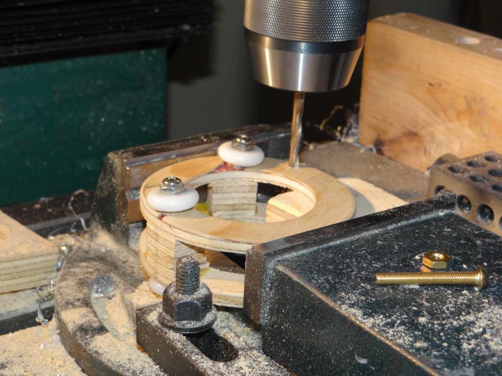
Once the hole position located, you will drill the hole through the focuser body rings. You can drill for a 10-24 bolt, or a little smaller or larger, whatever you have in your shop. Notice I placed a temporary cleat between the two rings so they would not bend during the drilling.
Then, I reunited the fine focus bracket and focuser body, positioned it correctly using the arc I had drawn previously as a guide, and, through the hole in the focuser body rings, I marked where I would drill the corresponding hole in the bracket body. I then drilled through the bracket body:
Notice that in this picture the fine focuser bracket has equal length sides. This was one of the first fine focus brackets I experimented with when first designing the prototype. This version did not work well so I rebuilt the better one which uses the brass bushings as described earlier. This is part of the pleasure (some would say frustration?) of designing things that have never been done before. You often go down a path which leads to failure. You learn from those failures and hope the next path will be better.
I make lots of mistakes so I learn a lot!
The assembly, at this point, looks like this. On this picture you can see that arc I mentioned above which I used to correctly position the two parts during drilling. You can also see the head of the 10-24 x 1.5 inch long brass bolt I used as a pivot:
Adding the Adjustable Friction Control
Some kind of a friction control is mandatory to use the DSHC focuser. This friction control plays the same role as the nylon or teflon tipped screw in a conventional Helical Crayford focuser. The only difference is that instead of pushing with the screw directly on the draw tube or coma corrector you instead push on the hinged fine focus assembly, which then transmits the pressure to the plastic fine focus rectangular slide, in turn pushing on the draw tube or coma corrector.
For the 3 inch aluminium focusers I first described in this webpage, I used a very discrete thumb screw which pulled against a home made plastic nut that was imbeded in the frame of the focuser:
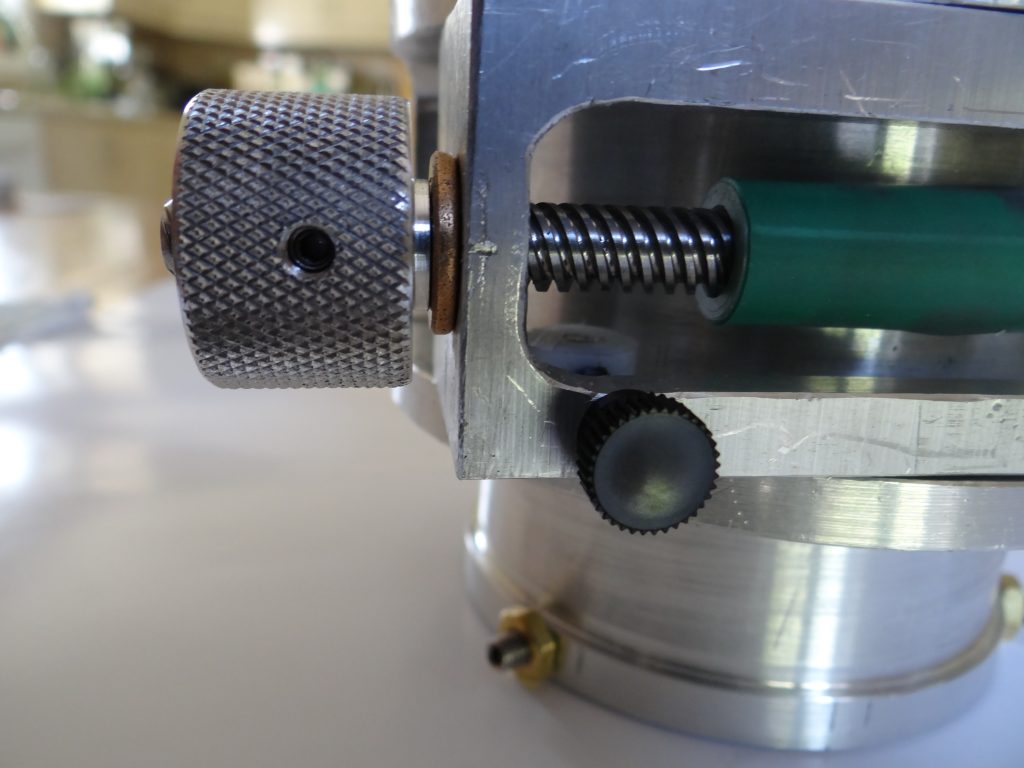
The friction screw is that little black knurled nylon knob. It goes through the aluminium fine friction frame and attaches to a white plastic “nut” (that white cylinder just visible in the picture) which pulls everything together. Friction is adjusted by tightening or loosening the black knob (the tighter it is the more weight the draw tube can hold but, the harder the fine focus knob must be turned to focus).
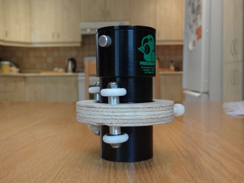
With the 2 inch plywood version of the focuser described here, I didn’t have room in the fine focus bracket assembly to drill a hole and position a screw the way I did with the 3 inch focusers. Instead I had to move the friction control mechanism above the fine focus bracket, as can be seen in this picture:
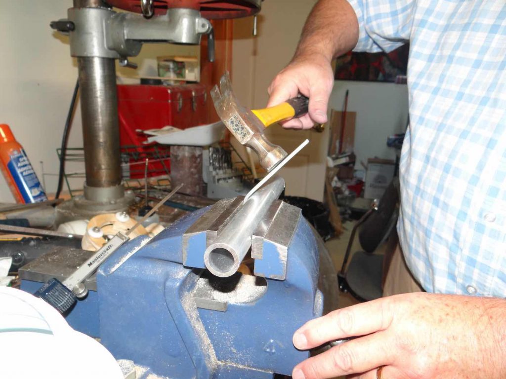
There are several ways of making this friction bracket but here is how I did mine. I used a 1/2 inch wide x 1/8 inch thick aluminium flat bar which I cut to about 7 inches in length. I then did a first bending pass in a vise using a 1 inch aluminium shaft I had lying around (you could use a broom handle if it’s more handy):
After the bracket had been bent a bit I remounted the part in the vise with the aluminium shaft now horizontal and used a hammer to complete bending in a U shape:
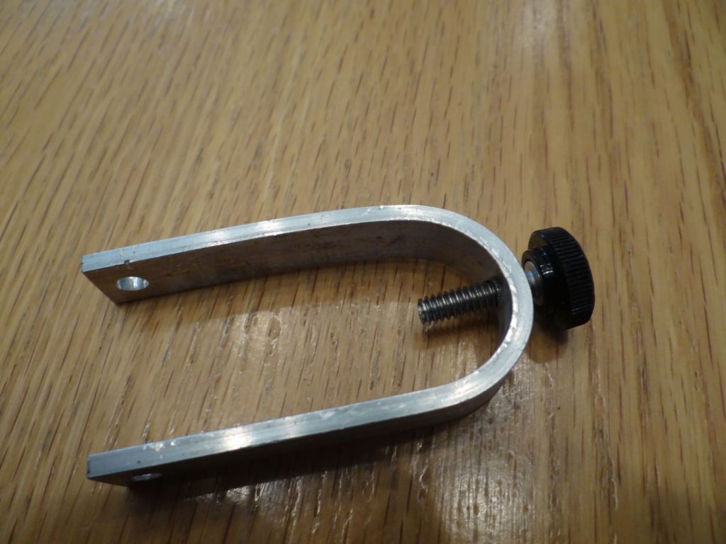
I then tried fitting it on the focuser body, opposite the pivot described in the previous post. After some rough calculations and trial and error I determined where to cut the friction bracket so it would correctly fit the focuser. I marked where I would drill the attachement hole at the bottom and proceeded to drilling, just like I had done in the previous post for the pivot.
I added a friction control knob (just tapped a hole at the top of the bracket) and the friction control knob looked like this:
It’s not the prettiest thing but it works quite well. The bolt at the bottom of the friction bracket must go through the frame of the focuser body, which is why the fine focus bracket had to have one of its sides partially cutoff. The friction thumbscrew must not push against the soft plywood top: the screw tip will dig in the plywood. Instead you should glue a small piece of metal where the screw pushes against the fine focus bracket. I used part of the aluminium flat bar I had cut away when making it.
CONCLUSION
I hope I was able to show how easy, and inexpensive, building a DSHC focuser can be with only simple tools. It would also be interesting to see, some day, someone making one of these through 3D Printing.