My Foucault/Caustic tester is very flexible. For example, the light source can be fixed or moving: It depends on which test it is used for.
Here is a view of the tester assembled to do the Caustic test:
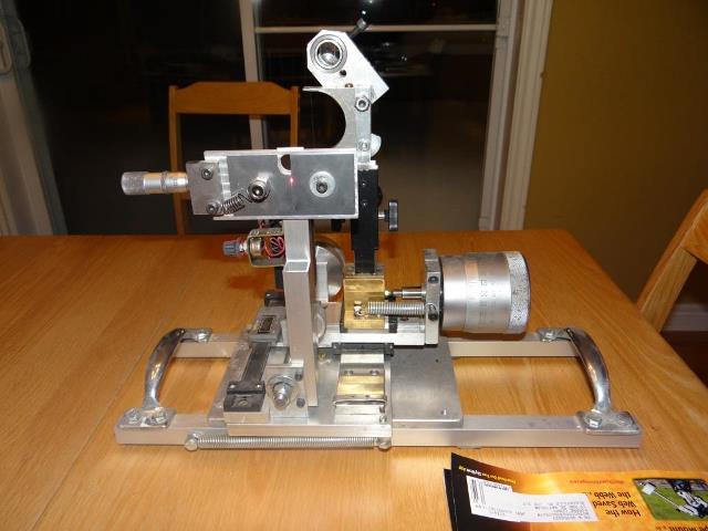
The light source, a high intensity red LED and its adjustable slit and power supply are one module than can be moved to either a fixed position in front of the test apparatus, or attached to the traveling X-Y-Z stage. When attached to its fixed position, the height of the light source can be varied to a certain extent by fixing it to one of half a dozen threaded holes in an aluminum square column at the front. This is the privileged position when undertaking the Caustic test. The wire, a very ordinary .005” diameter copper wire, is a strand taken from a larger gauge braded wire. It is mounted on a C-shaped frame. This C-shaped frame, along with a swing-in eyepiece to magnify the slit image and wire during measurements, is another module. When undertaking the Caustic or wire tests, this C-shaped frame is mounted on the vertically adjustable microscope stage, itself part of the X-Y moveable stage, where the light source would normally be attached for other tests like the Foucault or Ross. The position of the wire is such that when the large 1 inch travel x .0001” drum micrometer is screwed out midway, the wire is approximately centered with, and just behind the light source slit. The vertically traveling microscope stage is adjusted to bring the center of the wire about ½ inch above the light source and the angle of the wire can be adjusted to make it parallel to the slit (the slit angle itself can also be independently adjusted if required). The width of the light source slit is micrometer adjustable. The spring loaded sliding blade of the light source unit can be positioned in .001” increments relatively to the fixed blade. With a .005” diameter wire I’ve found a .007” slit width a good compromise for accuracy and light intensity. A small wire forces one to close the slit to maintain accuracy, diminishing light intensity. For example, I suspect a 0.003” slit width, needed for a 0.001” diameter wire, would make the slit images to dark, at least with the LED I’m using. And besides, I don’t see the advantage of using too small a wire (plus it is more fragile to manipulate).
Here is the tester assembled to do the Foucault or Ross test:

When the tester is converted to do Foucault or Ross, the C-shaped wire holder assembly is removed from the X-Y-Z stage and replaced with the light source unit. As mentioned above, the light source consists of a fixed and a moving scraper blade. As I’ve mentioned before on CN the scraper blades I use for the slit are made by OLFA, they are 45mmx45mm wide x 0.45mm thick and are absolutely the finest I have used for a Foucault tester (if you can’t find them at your hardware store, try www.princessauto.com , part # 8294027). Contrary to the Caustic test, the slit design becomes basically a “slitless” type, when used for Foucault or Ross. The moving OLFA scraper blade being used mainly as a “curtain” to limit glare and light bleeding out. The light intensity of the LED can also be adjusted through a potentiometer.
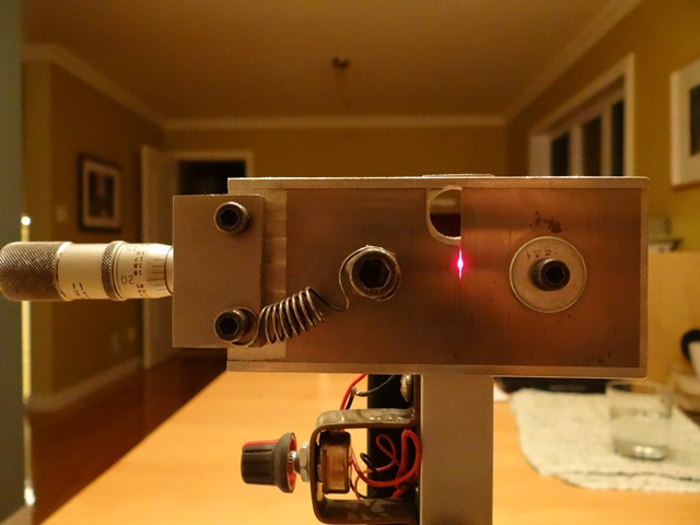
Here is a view of the adjustable slit as seen from the mirror side:
Other features of this tester: the longitudinal slide displacement is measured through a 6 inch digital scale attached alongside it. A large aluminum knob was turned and knurled so I could have a finer control over longitudinal movement. A 3/8 inch threaded rod, attached to the large knob is used for moving the carriage. There is no spring to pick up backlash so longitudinal movements must always be done in the same direction to pick up the backlash.
Here is a view of the 3 inch diameter, 1 inch travel X 0.0001″ drum micrometer used to measure lateral displacement, also showing the heart of the tester: the two linear bearing slides mounted perpendicular to each other on a machined aluminum plate:
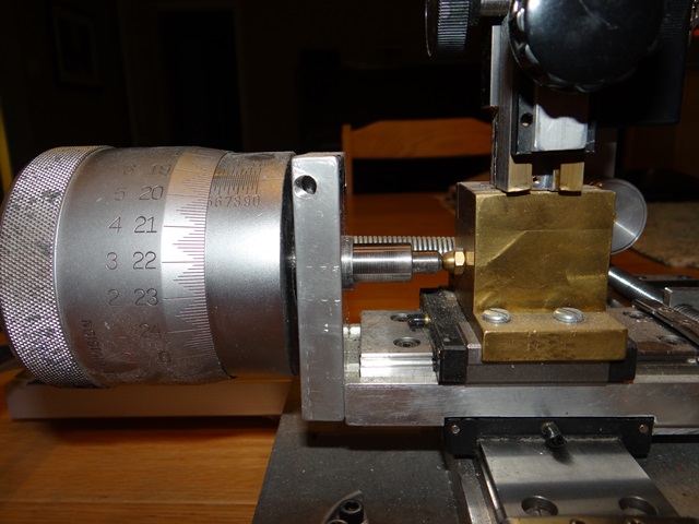
As mentioned above, the lateral movement is done through a large diameter micrometer screw with direct read 0.0001” accuracy (no vernier scale required). I think this screw came off a large optical comparator (got it at the Stellafane swap table 20 years ago for $20). I had it tested at the metrology lab at work and it is generating a maximum error of 0.000 03” over its entire 1 inch range. The center of the tip of the micrometer spindle pushes against a hemispherical acorn nut attached to the carrier. A spring keeps the micrometer and carrier in backlash free, constant contact. Finally, the entire tester can pivot in the horizontal plane around a center bolt to align the tester’s longitudinal axis with the optical axis. That rotation is controlled by the small micrometer at the bottom of the tester and just below the large .0001” micrometer. A long spring in front maintains rotational pressure to take away any backlash when operating this important adjustment.
The entire test unit weighs about 10 pounds and is very steady. It sits on four, hard rubber feet to prevent accidental displacement.
Discussion on testers
I’m not an expert in any of the tests that I’ve tried. I had made half a dozen mirrors before this one, with the biggest and fastest being a mediocre 12.5 inch F/5.2. I had not touched a pitch lap in 25 years when I undertook my 20 inch mirror. Because of this inexperience, I spent 18 months parabolizing my 20 inch f/3.9 mirror. This long delay provided the opportunity to try out some of these alternate tests. I am not happy with the final result on my mirror (TDE; too many scratches; primary ripple in certain locations; etc.) but, when I’m observing at 400x magnification and the image is holding up, I am proud of having produced this mirror myself. In two or three years, after I’ve honed my skills on a few new mirrors (including a 12.5 inch f/3 that’s in the planning stages), I will strip the aluminum off the 20 inch and start over. And this time, I will get it right!
So here are my observations after months of trials with the various tests:
Caustic
I think the Caustic, in the hands of a less experienced TM is more reliable than the Foucault when reading a zone. There is no doubt when the wire is centered in the image of the slit, a confidence I don’t have with fast mirrors and foucault readings. With the Caustic you are within plus or minus .0001 inch if your tester is well made. With the foucault I can easily move the knife edge .001″, or sometimes .002″ one way or another and it still looks right. So which one is the correct position?
Another advantage of the Caustic is that you know your measurement for that zone only after you have measured the second slit position and calculated the difference. With the foucault you are only reading one number for each zone, which you end up memorizing after a while. I found this could bias my judgement. No such danger with the Caustic.
Ross Null Test (Foucault)
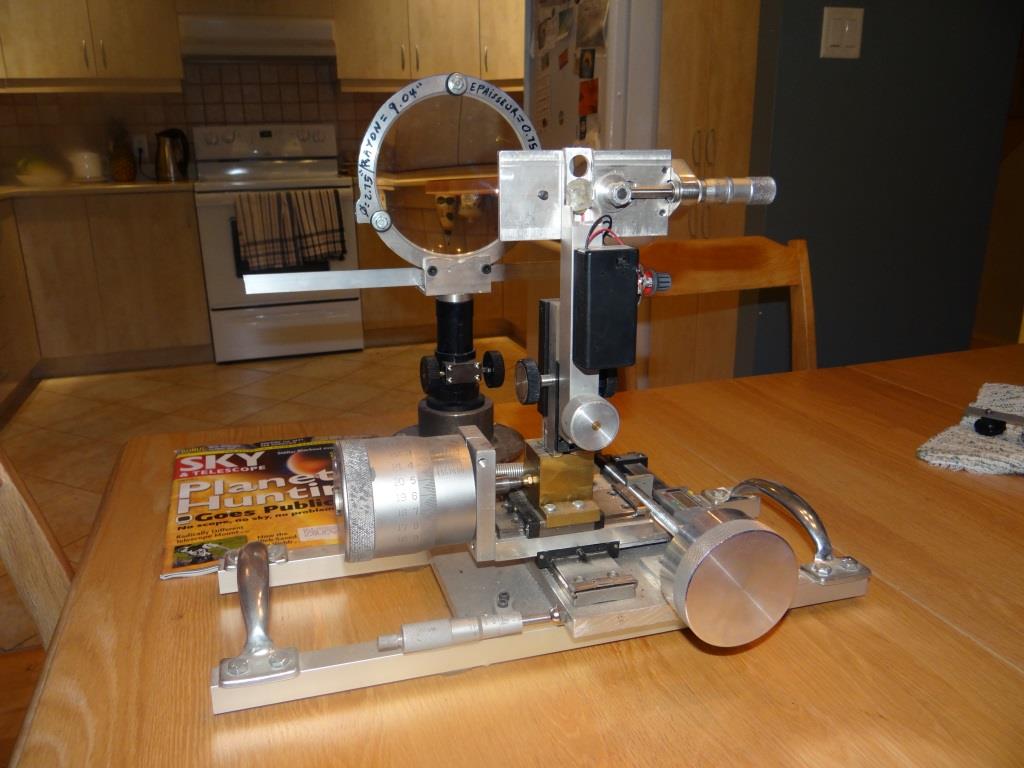
Here is a photograph of the tester setup behind a Ross Null lens compensator. The plano-convez lens is over 6 inches in diameter but only the central 2.75 ” central portion of the lens is of high enough quality to accurately test a mirror (as measured by Optician Peter Ceravolo).
I found it difficult to use the Ross null test in combination with the Foucault (as opposed to the Ronchi, see below). Adjusting the position of the lens was the key and, according to my calculations, I needed to position the compensation lens within a precision of something like .030″ of the mirror to get a correct surface when finished. Over a length of 10 feet, that’s pretty tight, which is why I made the threaded rod system described earlier.
Although I could lift, rotate and tilt the lens, I found the tilt mechanism was the weak point. Tilting was done with a small screw at the base of the lens holder. Unfortunately, because of this, tilting would also rock the lens forward or backward because it was pivoting from the base. For future testing I will move the tilt mechanism near the center of the lens.
Also, I couldn’t entirely trust the 6 inch diameter plano convex lens. I had purchased it following the Ceravolo article in Telescope Making magazine from someone who had gotten a batch of them. Peter had measured each lens sold (they were selling for $20) and indicated the reliable central portion that could be used. Mine came with 2.75 inches diameter of reliable surface in the center but my calculations for the 20 inch indicated I would normally need at least 2.90 inches.
Ross Null (Ronchi)
In it’s ronchi screen version the Ross null is much easier to use. Although it is not quantitative, it is one of my favorite tests. Unlike the uncompensated ronchi, which requires an interpretation of the curvature of the bands, all you need to do with the Ross lens is work until those bands are straight. I still had the lens-mirror distance challenge to control but interpretation of the bands was very intuitive. Also I could take a picture of the ronchi lines and analyze them with Microsoft Paint, by superposing a straight line over the band images and compare the straightness of the bands to the line. I suspect that if you worked only with this test you could make a decent light bucket. However be aware that the Ronchi is not a very accurate test unless you “magnify” the bands (i.e. place the ronchi screen very close to the center of radius) to show only 2 or 3 of them. If you are going to do that, may as well use the Foucault.
Star Test
I still have a long way to go to improve my skills with the star test. I fear a lifetime (at least what’s left of it) will not be enough for me to grasp all the subtleties! But that is the beauty of this hobby: there is always something to learn if you actually give yourself the opportunity to try, fail, and try again.