Building the First DSHC Prototype
INTRODUCTION
Over the years I have built a number of focusers, including: Threaded Helical, Conventional Crayford and Helical Crayford (HC) focusers. Since many of my telescopes are portable and need as lightweight as possible Upper Tube Assembly (UTA), I’ve come to particularly appreciate the lightweight and very smooth working Helical Crayford focusers.
However, as lightweight and smooth as they are, the HC focusers present a few disadvantages which become particularly apparent when used on short focal ratio instruments and with larger, and heavier, eyepieces and optical accessories.
The first disadvantage has to do with the necessity of tightening down the pressure screw, whose role is to push the eyepiece draw tube against the four inclined ball bearings that provide the linear movement focusing action. This pressure screw (normally plastic or Teflon tipped) does not have to be tightened down too much when using a lightweight, 1.25 inch eyepiece. But when one scales up to 2 inch eyepieces, things get more complicated. Indeed, some of these 2 inch eyepieces can weigh as much as 2.5 pounds, or more. In addition, on Newtonian telescopes, a coma corrector is often used which adds at least an additional pound but also lengthens the eyepiece stack far above the focuser base, creating a strong torque on the base.
Another disadvantage with HC focusers is that the speed of focusing, determined by the ball bearing axis of rotation angle, is fixed. It’s one thing to focus an f/6 instrument which has a fairly long depth of field of acceptable focus. On the other hand, an f/3 instrument will require a much finer focusing movement. If the focusing movement is made too fine, changing eyepieces or observers could require many turns of the draw tube to cover all possibilities.
For many years now, classical Crayford Focusers (CF) have been offered with an optional fine focusing knob which uses an internal, planetary ball bearing mechanism to provide the focuser with both a coarse focusing knob and a fine focusing knob. Inherently, the HC focusers are also dual speed focusers since it is possible to slide the draw tube in and out for coarse focus and rotate the draw tube for fine focus. However this is not always practical for heavier eyepieces since the plastic tipped pressure screw must first be relieved of the pre-adjusted pressure, then re-tightened to do fine focus.
Mel Bartel’s 25 inch telescope
Sometime in 2017, well known ATM Mel Bartel, working on a new 25 inch f/2.6 newtonian telescope, mentioned to me how expensive it was to get a proper 3 inch focuser for his new telescope, which he was hoping to use with a 3 inch Paracorr coma corrector and 2 inch eyepieces. I offered to build Mel a conventional 3 inch HC focuser, a pretty simple endeavour for me since I have all the machine shop equipment at home and I had built a number of these over the years.
But, as I started working on the design, I went back to some sketches I had made over the years to try and solve some of the HC issues I discussed in the introduction. There must be a way to provide the HC focuser with a similar fine focusing option, like the one sold for Crayford Focusers. One evening, in early December of 2017, I finally had that Eureka! moment: I finally figured out a way to provide the HC focusers with that fine focusing mechanism that had always eluded me.
The great thing about this clever idea is how simple it is to make. That’s what I would incorporate in Mel’s focuser.
The Dual Speed Helical Focuser (DSHC) mechanism
The DSHC mechanism is extremely simple to make. Quite frankly, I’m surprised no one ever thought of doing this before. Here is the basic Working principle:
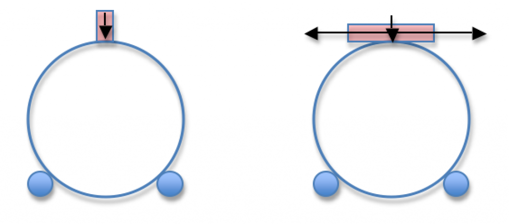
On the left is the working principle of a Helical Crayford focuser. The large draw tube (blue ring) rests on four ball bearings (small blue discs, below) and a plastic tipped screw (pink rectangle on top) pushes the draw tube onto slightly inclined ball bearings with a constant pressure. To focus, one rotates the draw tube which moves in or out, as required. The slight inclination of the ball bearing axis creates an imaginary « helical thread » which the draw tube follows.
On the right is the working principle of the DSHC focuser. The main difference is that the plastic tipped screw has been replaced by a sliding plastic cylinder, mounted on a long screw. The axis of rotation of this cylinder is perpendicular to the optical axis. To focus, one first rotates the draw tube, which moves in or out, as required (just like one would with a conventional HC focuser). But, once close to focus, the observer reaches for one of the focusing knobs attached to the plastic cylinder and rotates one way or another. What this does is it allows the observer to finely control the rotation of the draw tube to achieve a much more accurate positioning of the eyepiece with regards to the telescop’s optical focus position.
A rectangular, rather than round, friction cylinder.
Although I mention using a moving cylinder for fine focus, I discovered at one point that a cylinder was not a good idea due to the small surface area in contact with the draw tube. Indeed, two cylinders that intersect perpendicularly contact each other at a single point. To increase the surface area I switched to a rectangular, rather than circular, fine focus “cylinder”. Unfortunately, since I discovered this fairly late in the project, most pictures on this web page show a round cylinder. If you are considering making one of these, disregard the round cylinder. Here’s what that friction assembly now looks like and what I recommend for maximum grip:
A few pictures
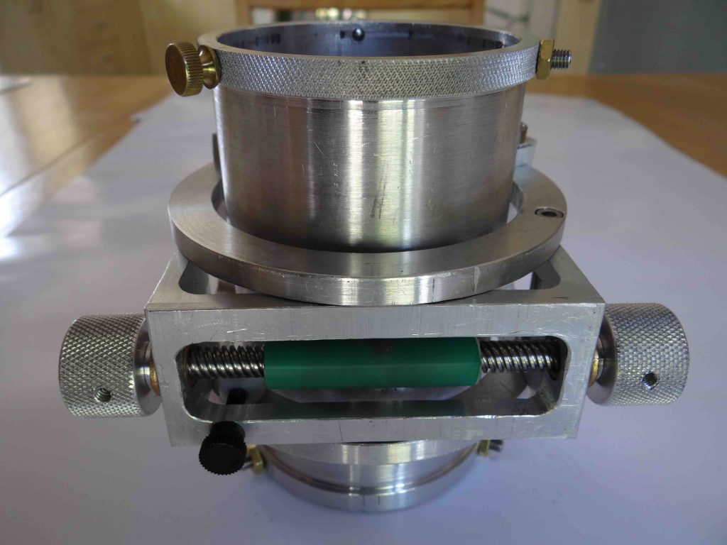
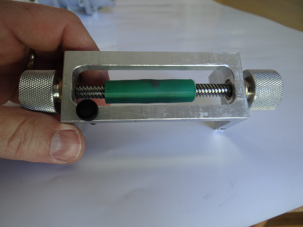
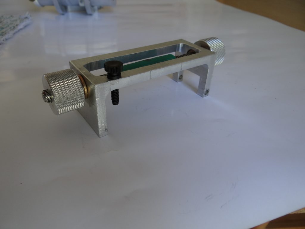
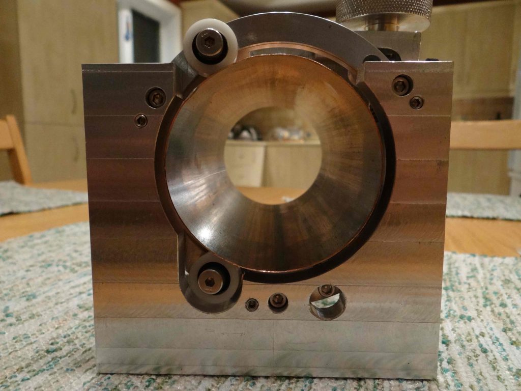
The picture above shows the fine focus mechanism of a 3 inch DSHC focuser. The green cylinder in the center is moved from side to side by the central lead screw connected to the two knobs on either end. Pressure between the cylinder and the draw tube is applied in a constant fashion by the small black knob on the left. The entire fine focus mechanism is mounted on a hinge.
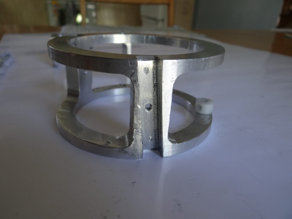
The image above shows one of the two pairs of angled ball bearings on the back side of the focuser. The angle of the axis of rotation of those bearings is what produces the smooth focusing action of the draw tube during rotation.
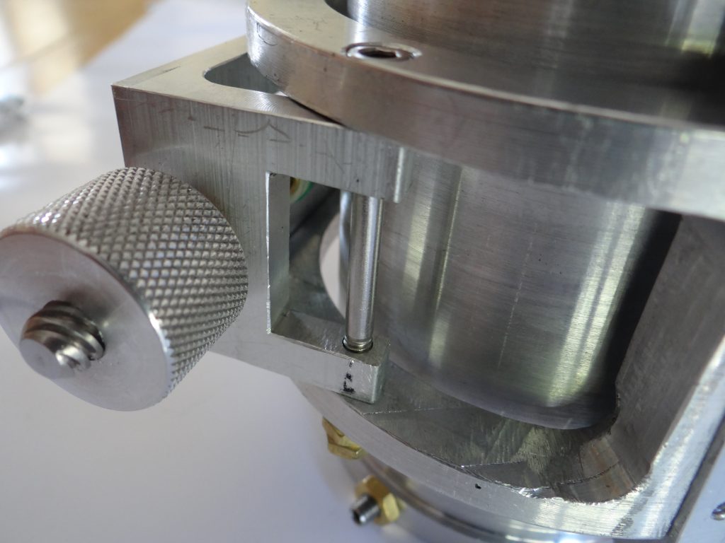
In the above picture we can see how the fine focus bracket is attached to the frame of the focuser through a hinge mechanism. The hinge is a simple machine bolt.
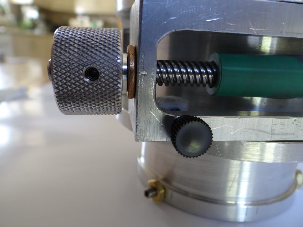
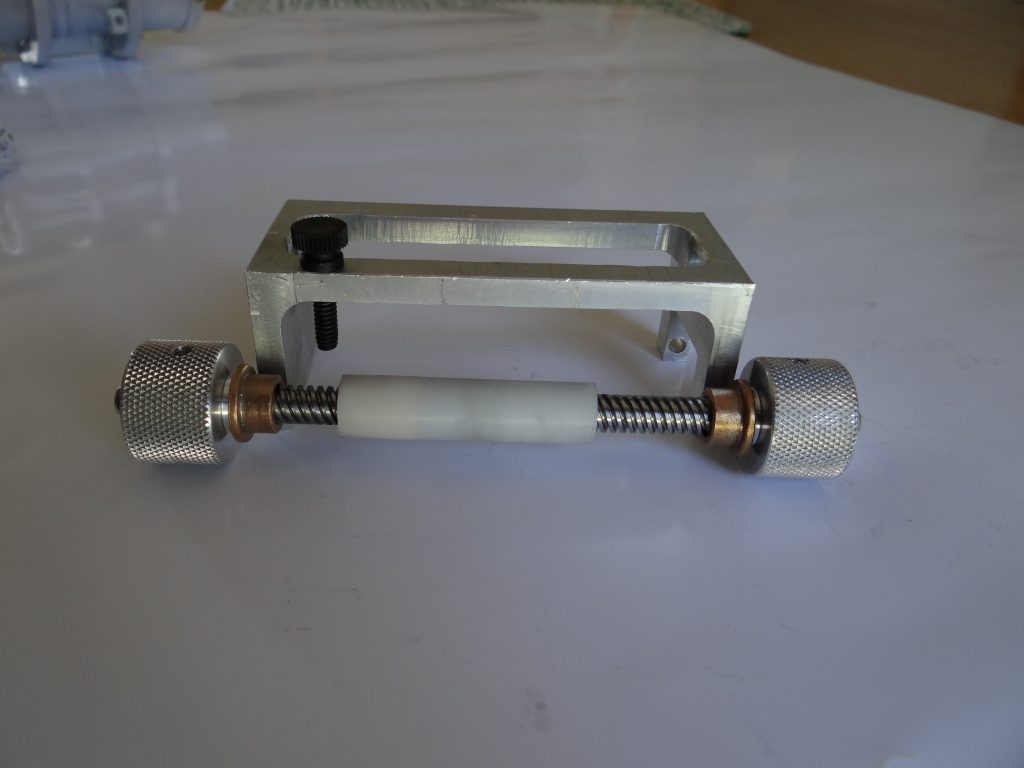
In the above view we see the opposite end of the fine focus bracket. A black nylon thumbscrew screws into a specially machined delrin nut (white cylinder below the lead screw). This is how friction between the fine focus cylinder against the draw tube is adjusted. The adjustment must take into consideration the weight of the eyepieces and other optical accressories mounted on the focuser. The heavier the equipment, the tighter the thumbscrew must be turned but the harder it gets to turn the fine focus knobs.
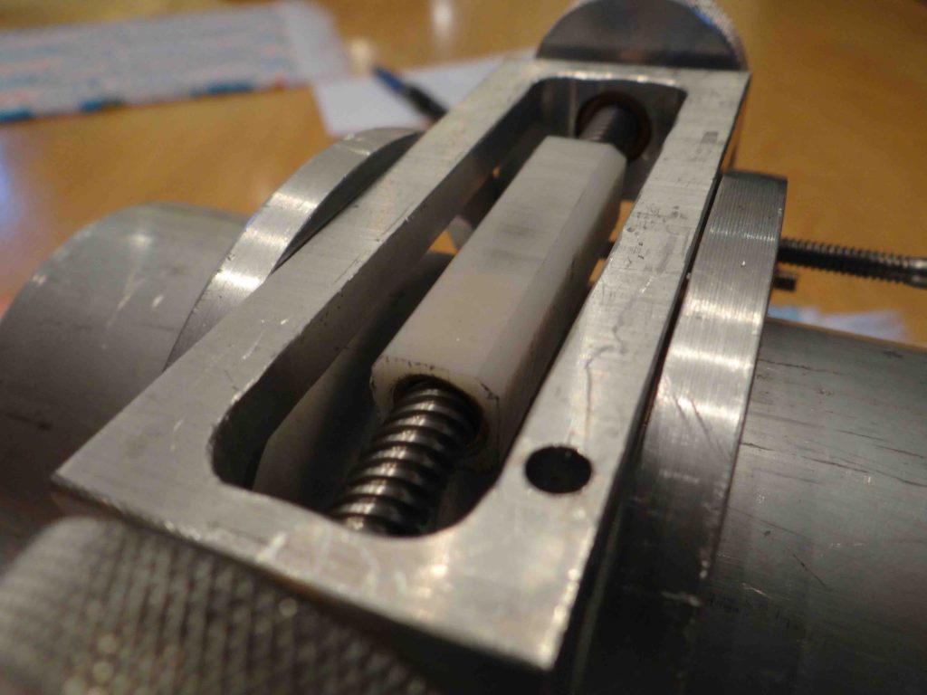
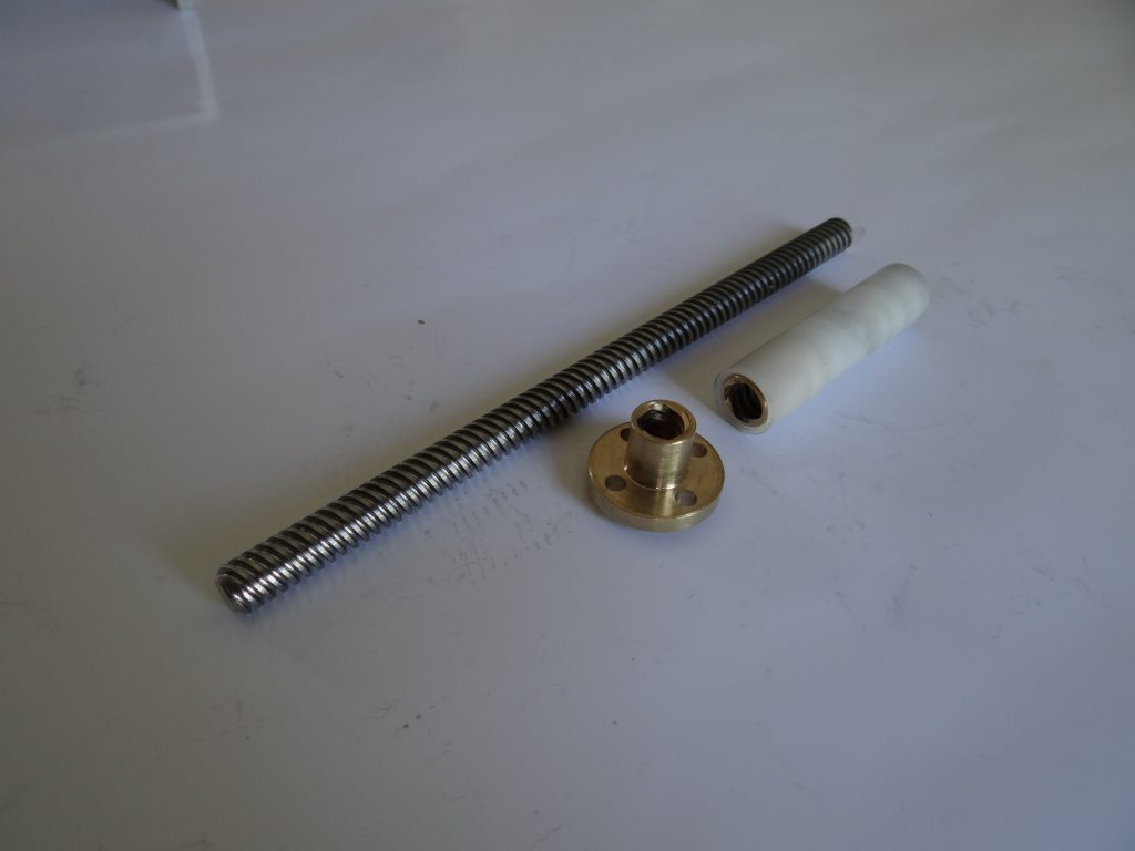
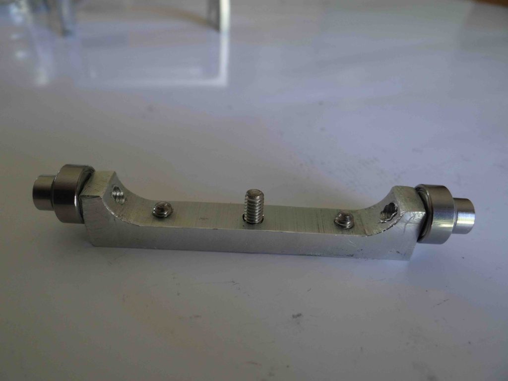
Here are two views of the disassembled, fine focus bracket unit:
And another view of the fine focus bracket, this time with the screw and cylinder removed from the bracket. Notice that in this picture I’ve removed the green heat shrink tube I was experimenting with to increase friction but came to the conclusion that contact with the Delrin cylinder was fine:
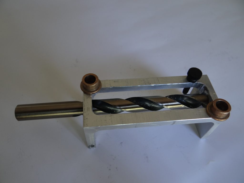
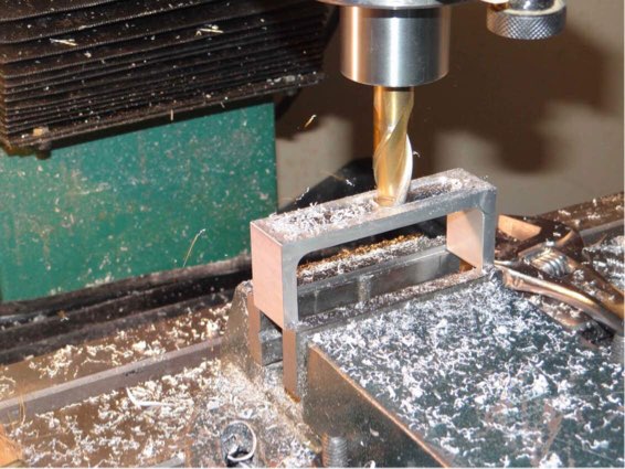
This picture shows how the oilite bushing cavities were drilled in one pass with a 12mm drill bit that matched the OD of the bushings:
In the following picture we see that part of the fine focus cylinder was drilled with a 8mm drill bit corresponding to the OD of the stainless steel lead screw:
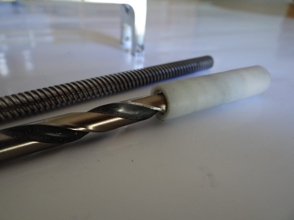
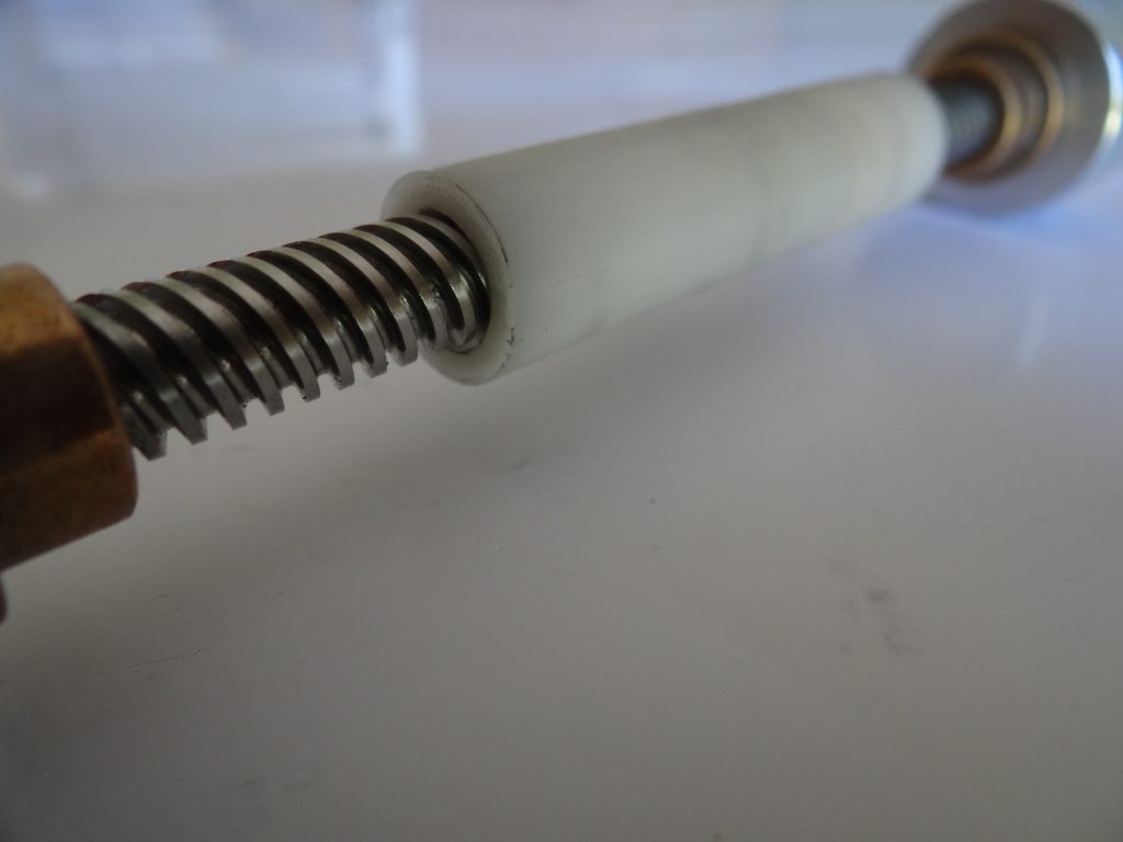
And, at the non threaded end, the fine focusing cylinder simply rides on the lead screw’s outside diameter:
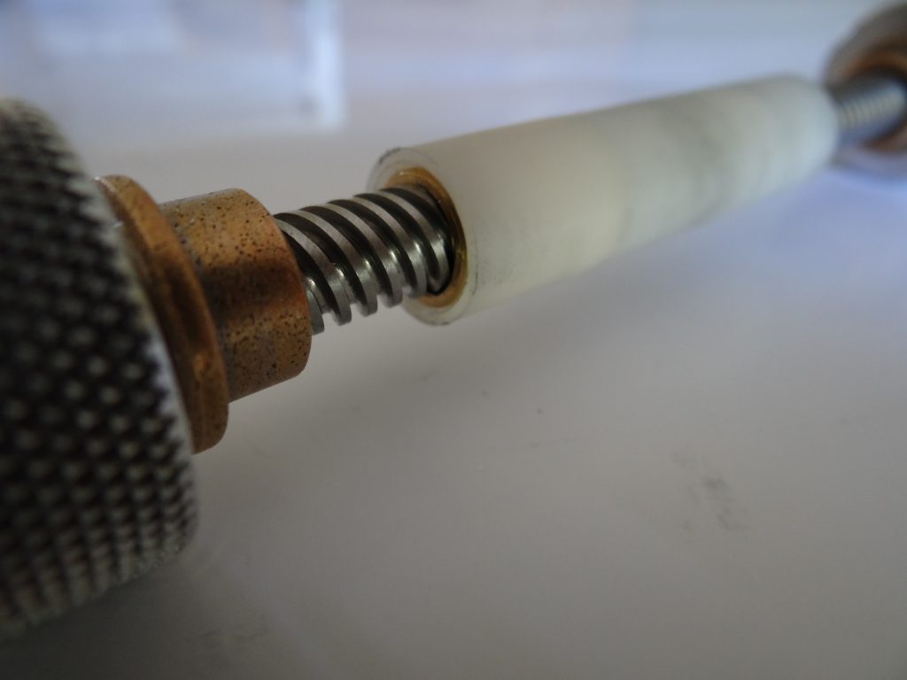
The other end of the cylinder received the threaded insert which came with the lead screw:
These lead screws and bushings are available on Ebay for about 4$ per set 6 inch long screws). Just type in T8 lead screws and look for 8mm pitch. These have four, multiple start threads which results in a linear movement of 8mm (about a third of an inch) per rotation of the lead screw. The threads must be very coarse. A 1/2 inch NC 13 thread per inch is too fine and will be frustrating to use. It would take many rotations of the fine focusing knob to reach focus.
The flange seen on the original threaded insert was machined out to a constant diameter. A hole was drilled in the delrin cylinder at a size to allow an inteference fit of the bushing with the cylinder. The interference fit is a little too tight at the moment and the cylinder bulges by about 0.006 inches more in diameter than the rest of the cylinder. This may have to be redone because the fine focus tightens up unequally, depending on which end of the cylinder is in contact with the draw tube. On the other hand an interference fit is needed to prevent the brass threaded insert from slipping inside the drilled cavity in the delrin. Some experimentation will be required to determine the optimal interference fit.
Here is a view of the threaded end of the fine focus cylinder showing the threaded bushing engaging the lead screw:
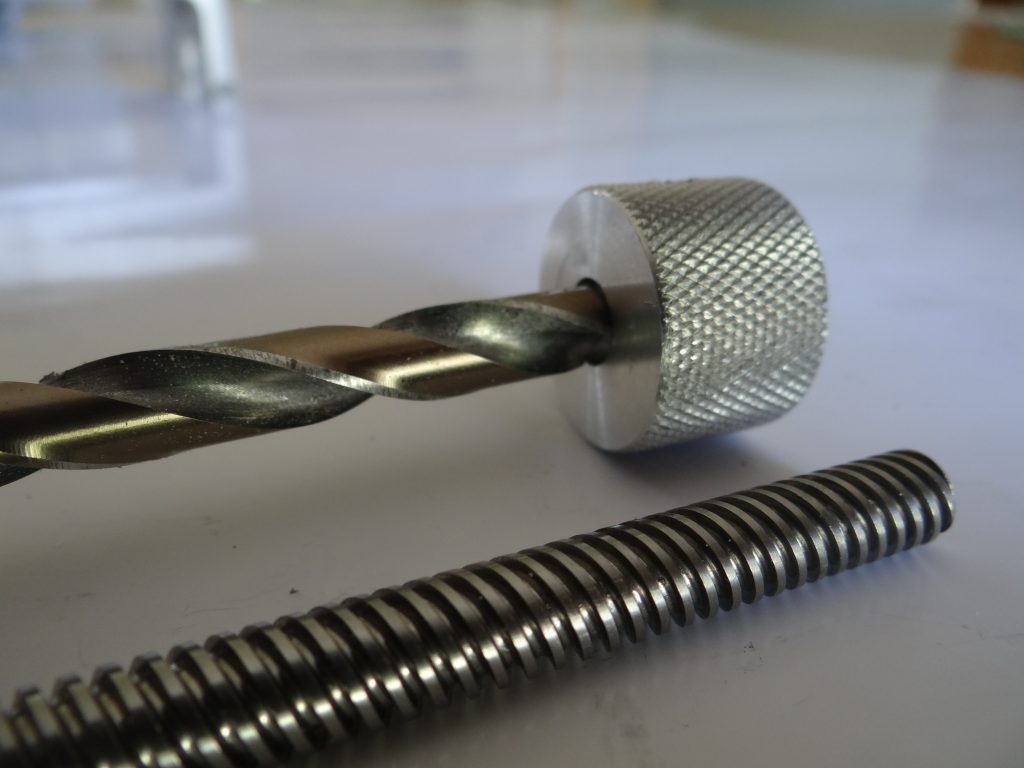
The same 8mm drill bit used to partially drill the delrin cylinder was also used to drill the two focusing knobs:
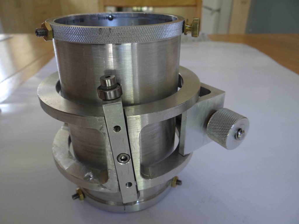
Here is a view of the focuser body by itself:
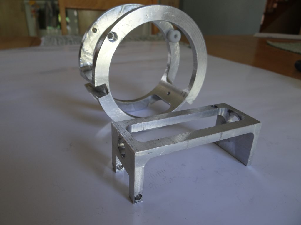
And an image of the two main focuser parts that, if 3D printed, could make the assembly of the focuser much more accessible to those wishing to use this focuser on their telescope:
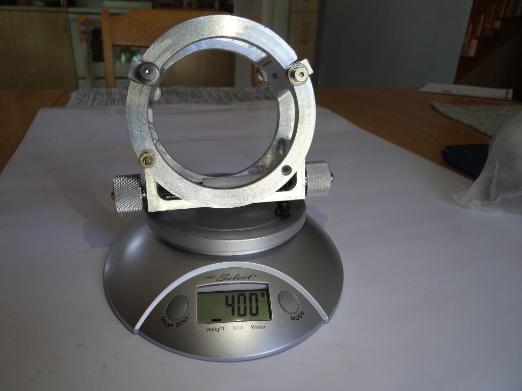
Here is a photograph of the focuser body without the draw tube on a kitchen scale. By itself it weighs 400 g, or about 0.9 pounds:
And the entire unit, with the 3 inch draw tube, which weighs 700 g (1.54 pounds):
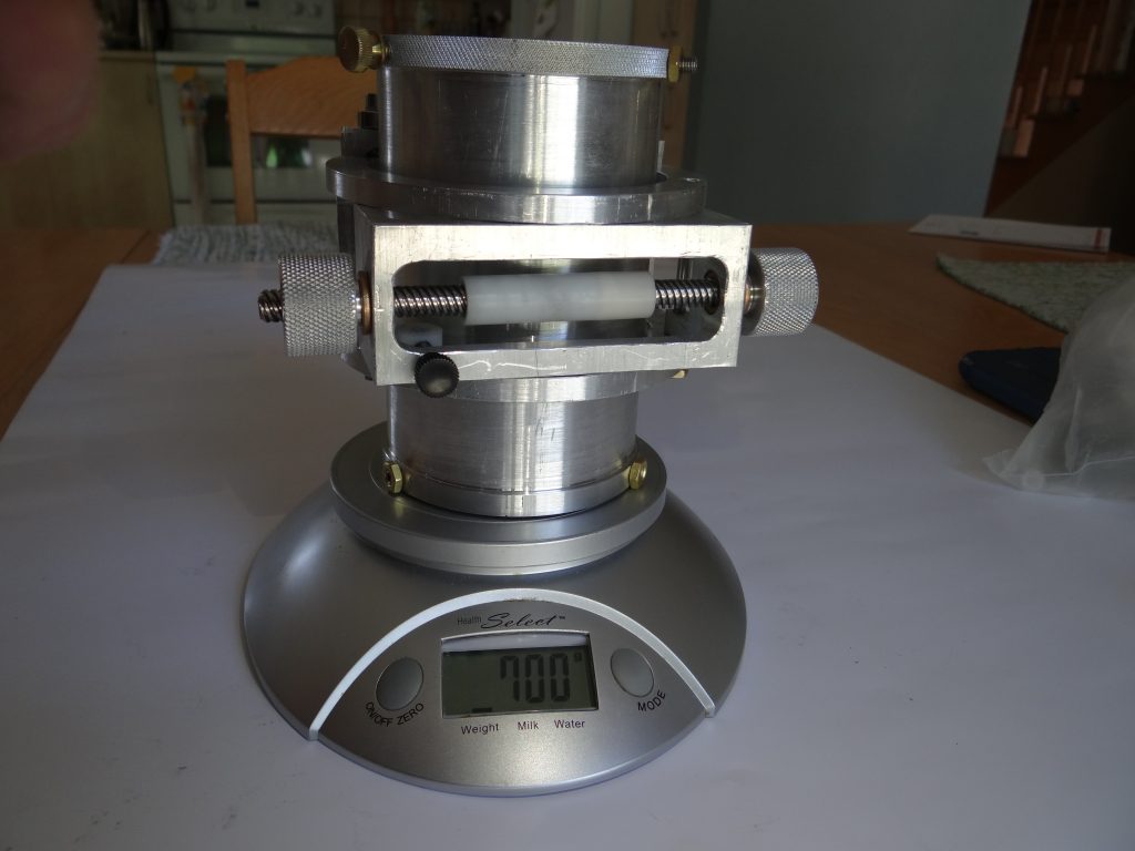
Not bad, considering this is a focuser for 3 inch eyepieces!
Since this type of focuser will often be used with short focal ratio telescopes, a coma corrector will frequently also be necessary. Because of the way it is built, the DSHC does not require a draw tube if a coma corrector is used since the coma corrector’s cylindrical body serves as a perfect draw tube.
It is important to note that when using a Helical focuser, the eyepieces and accessories mounted in the focuser must be perfectly centered and concurrent to the draw tube, unlike a normal Crayford focuser. This is because the eyepiece rotates and a non-centered eyepiece would be impossible to collimate in all focus position. The advantage of mounting the coma corrector directly on the focuser eliminates any wobble. However, if a draw tube is to be used, collimation screws must be used to center the coma corrector. The draw tube in the images show 5 collimation set screws with hemispherical tips in order not to scratch the coma corrector. The sixth screw is the thumbscrew that tightens the CC to the draw tube.
In this picture we see one of those setscrews and locking nut:
It’s hard to see on the photo but the tip of the setscrew his rounded to prevent scratching the surface it comes in contact with.
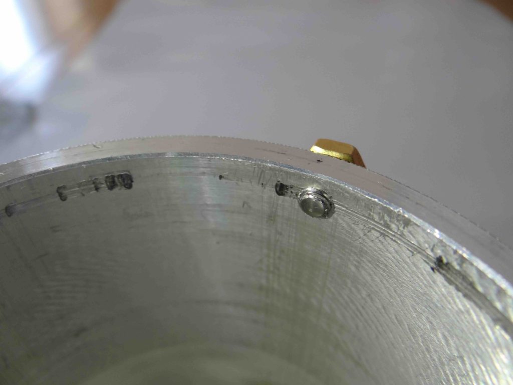
This picture shows one of the two bearing support brackets that lodge in the inclined slots in the focuser body:
You will notice that there is a central bolt which attached the bracket to the focuser body. Also, on each side of the central bolt are two set screws. Over the years of making these HC focusers, I found frustrating not to be able to adjust the centering of the draw tube in the focuser body. Those two set screws allow that adjustment.
To prevent marring of the draw tube or the coma corrector body I did a test with Delrin ball bearings of the same diameter as the Stainless Steel bearings show in the previous picture ( half-inch bearings). This was unsuccessful. The Delrin bearings are too fragile to stand the pressure of the large focuser. They would probably, however, work with a 1.25 inch focuser.
Since the half inch Delrin bearings were not strong enough, I ordered some 3/4 inch diameter ones:
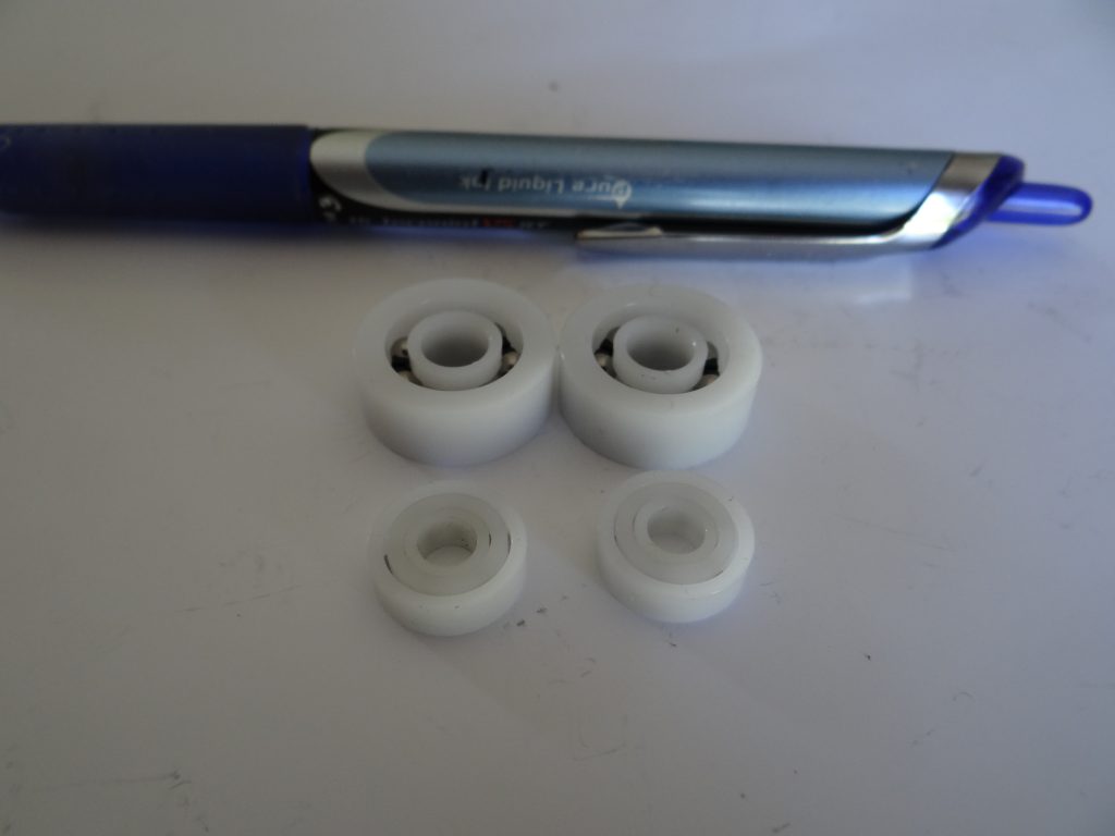
These are much more robust and are able to sustain the stress from the friction imposed to the fine focus roller to hold heavy eyepieces.
Specifications
I tried to get as close as I could to the initial specifications Mel was looking for and completed with requirements I consider important in this type of accessory.
Here are the principal specs:
- Maximum Focusing range: 1.5 inch
- Rough focusing speed: 0.9 inches of travel in one rotation of the Draw Tube
- Fine focusing speed: 0.028 inches of travel in one rotation of the fine focuser knobs (a 1:32 coarse-fine focusing ratio)
- Fine focusing range: 0.125 inches
- Total weight of focuser: 1.5 pounds (Focuser body: 0.9 pounds; Draw Tube: 0.6 pounds)
- The fine control screw is a T8 lead screw with four thread starts for a pitch lead of 8mm (one turn of the nut moves it 8mm or about 1/3 inch).
The focuser works well, with very little slop. When I reverse direction of the fine focusing knob I can measure a 0.000 5″ to 0.000 8″ of backlash, probably traceable to the nut and lead screw looseness being taken up. Remains to be seen if this will be a problem in use.
Mel Bartels’ 3 inch DSHC Low Profile Focuser
The first 3 inch DSHC prototype focuser I made for Mel Bartel’s 25 inch telescope turned out to have too high a profile for his focal plane position. I decided to keep that one for a future project and start another one.
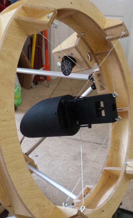
Mel normally mounts a 2 inch Moonlite Crayford on a right angle wooden bracket attached to the top, Upper Tube Assembly of his 25 inch. You can read more about Mel Bartels’ innovative 25 inch telescope on this web page. The focuser right angle bracket can be easily removed and interchanged with another instrumentation bracket support if needed. The back of the bracket is visible in this picture, just above the wire supported diagonal holder, holding a laser collimator:
To minimize the obstruction caused by the larger right angle bracket that would be required for the larger, 3 inch focuser, I chose to make the interchangeable right angle bracket out of aluminium. More on the construction of that bracket later in the text.
In order for this aluminium bracket to be interchangeable with the 2 inch focuser, I had to fit exactly the same bolt pattern Mel had used for the 2 inch focuser. Also, of course, the optical center of the 3 inch focuser had to perfectly match the optical center of the 2 inch Moonlite Crayford and, the position of the focal plane had to be located at least a half inch above the fully racked in 3 inch Paracorr flange when inserted in the the 3 inch focuser. Finally, provision to align the 3 inch Paracorr’s optical axis within the focuser would be incorporated into the attachment of the focuser to the bracket, to minimize collimation when switching focusers.
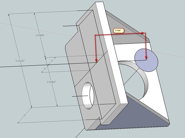
Mel sent me this simple drawing which provided all the requirements I needed for guidance:
So, with more accurate data in hand, I built a second unit, better adapted to his instrument. I also learned a thing or two from the first unit allowing a simplified machining procedure.
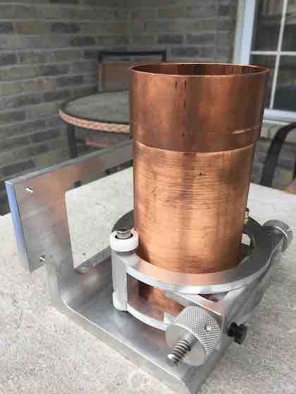
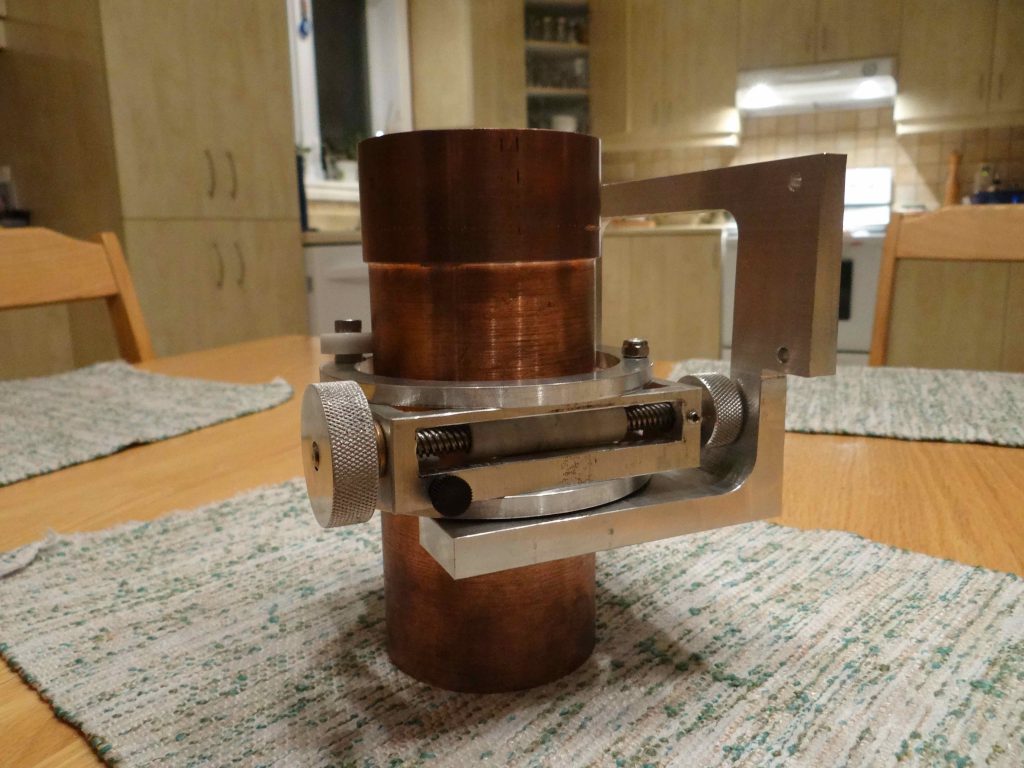
Here is what the new unit ended up looking like:
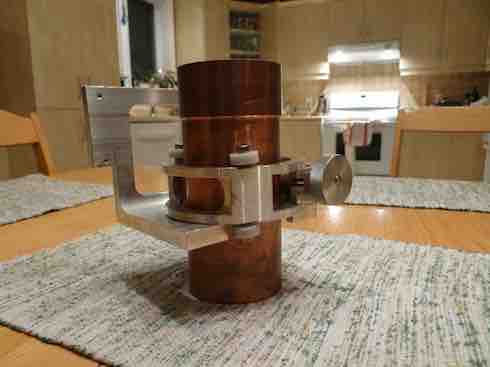
The copper tube is something I had lying around in my scrap bin. I machined it to a 3 inch OD to be used as a substitute to the 3 inch Paracorr which I didn’t have access to.
Attaching the bearings directly to the focuser body
Instead of attaching the bearings at the end of two short beams like I did for the first prototype, and like I’ve always done on all Helical Crayfords I’ve made in the past, I decided, instead, to screw the bearings directly to the focuser body.
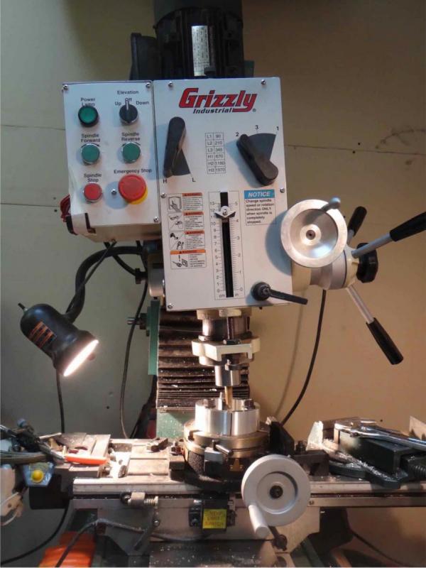
To do this, I installed a rotary table on my milling machine and inclined the milling head at an angle of about 5.5 degrees. This angle provides a rough focusing speed of about 0.9 inches per draw tube rotation. It felt about right for a 3 inch focuser but it could vary a bit. Choosing the bearing incination axis is a compromise of sorts. If too fine, the fine focus movement will be too fine as well, even with the course fine focus screw I’m using. If too course the draw tube will go up and down too fast and be harder to rough focus.
The same operation shown here could be done with a drill press but it’s the drilling table that would be adjusted with a slope instead of the spindle. I preferred to use my milling machine for this operation. Also, drill presses are not designed to do milling operations. The chuck could loosen and fall (ask me how I know this!). However the milling job shown here is very light and would probably be OK for most drill presses.
I cut a 1.5 inch thick slice of 4.5 inch OD by 3.5 inch ID aluminium tubing (same tubing I used for the first prototype), turned and faced it in the lathe to make it all square and concentric and centered and bolted it to the rotary table.
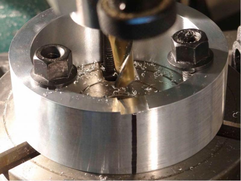
Before starting the first cut to generate a flat, inclined surface on which the bearings would be tightned against, I first carefully measured the ID of the tubing. Knowing the 3 inch Paracorr has an OD of 2.997 inches, I traced a quick sketch in Autocad and determined where the threaded holes for the 3/4 inch Delrin bearings would be drilled and tapped, resulting in as concentric as possible positionning of the Paracorr relative to the focuser body.
I then traced a datum line (seen in the picture, below) to know where to cut/drill the first bearing. I then used the rotary table’s indexing handle to position the bearing flats 120 degrees away from each other. Using a half-inch end mill, I cut inclined flats on which I would drill the hole for the machine bolts that hold the bearings to the focuser body.
I then flipped the focuser body upside down, recentered it on the rotary table and repeated the procedure to generate the corresponding flats on the opposite side.
After machining four inclined flats on which the bearings would sit, I then used the milling machines’ adjustable table to position the exact location of where to drill the holes that would receive bolts serving as shafts for the bearings. I then drilled those four holes, using the rotary table to rotate 120 degrees:
The four holes were then hand tapped:
Here is what the result of adding those four bearings directly to the focuser body looked like. You will notice that to test the system, I just added a temporary nylon screw opposite the four bearings, essentially making this a giant, 3 inch Helical Crayford focuser:
The next steps were heavy machining of the focuser body. Purpose was to cut a 1 inch wide slot across almost 2/3 of the focuser body, to receive the hinged fine focus bracket and reduce the weight of the focuser as much as possible. I also removed a 1 inch wide slot on the opposite side of the main slot for weight reduction purposes. The end focuser body is basically two 1/4 inch thick rings attached together by two beams, 120 degrees apart, on which the inclined bearings are mounted:
And the following steps were to take a 1.1 inch wide slice out of a 1 x 4 inch U-Chanel, machine it to 1 inch wide so that it tightly fit in the focuser body slot and drill the holes for the bushings, just like I described in my first post:
One special thing I had to take into consideration for this lower profile unit was to leave enough material to insert the black nylon friction screw. I could not center the lead screw in that bracket. If I had, the nylon screw would have interfered with the lead screw. So I offset the lead screw to one side to provide enough room on the other side for the friction adjutment screw.
In this picture you can see that offset position of the leadscrew I mentionned above and how the black nylon friction screw does not interfere with the fine focus Acetal cylinder:
Making the Aluminium Right Angle Bracket
I wen’t to my local metal supplier and found a 1/2 inch thick x 6 x 6 inch extrusion that was perfect for this application. I had a 7 inch wide section cut and started machining operations on the milling machine. I first cleaned up the outside, right angle surfaces and made sure they were perfectly perpendicular (this extrusion was not perpendicular when I got it).
I then drew a line with a felt marker through the center on both outside faces to provide a datum and measured, and carefully marked, the position of the four mounting holes. Using the same line, I also marked the position of the center of the optical axis. With the milling machine’s X and Y positioning screws, I then proceeded to drill the four 3/16 inch diameter mounting holes. I then turned the part right angle and drilled a 3/16 inch pilot hole for the optical axis. Without disturbing the milling setup, I then progressivly used larger and larger drill bits to increase the hole diameter for the optical axis to one inch, which is the largest drill bit I have.
After these hole positionning operations, I then did some metal removal operations with a large end mill to reduce, as much as possible, the weight of the aluminium bracket, thus that big empty rectangle in one of the sides.
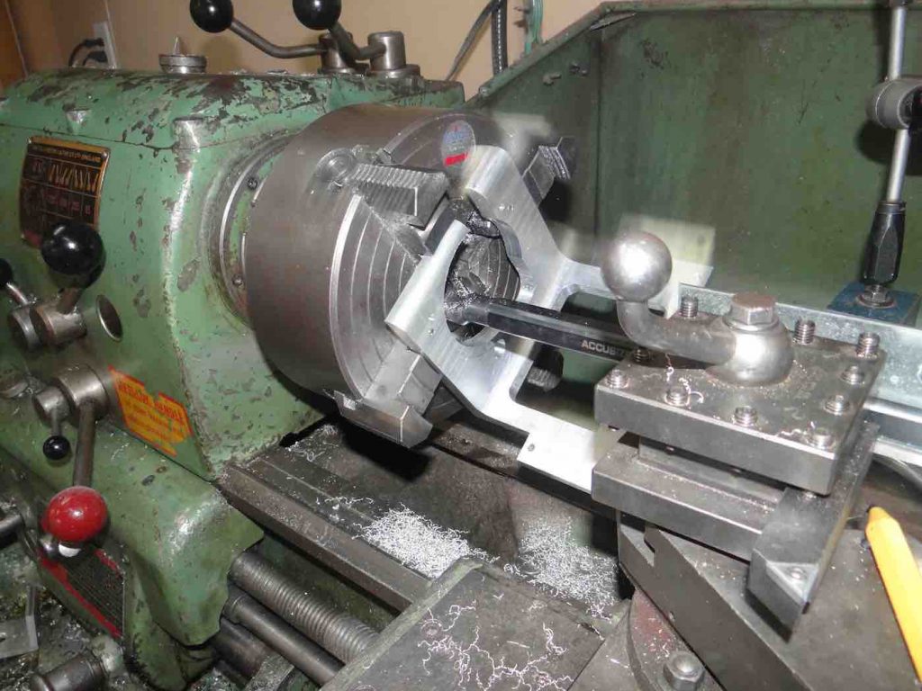
I then transferred the right angle bracket from the milling machine to my lathe. I used a four jaw chuck and the 1 inch drill bit to center the part in the lathe:
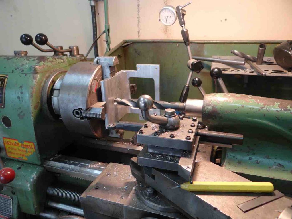
Using my long boring bar I increased the hole diameter to 3 inches, just enough so that the 3 inch copper pipe I was using as a substitute for the 3 inch Paracorr, would fit tightly:
I placed the 3 inch focuser on top of the bracket with the 3 inch copper pipe sticking through the tight fitting 3 inch hole. Here is a picture of that assembly when I briefly considered placing the fine focusing knobs perpendicular to the optical axis:

This was not the most ergonomic position for the fine focus knobs but made it easier for for me to machine the right angle bracket to accommodate the two bottom delrin ball bearings. In the end I found a way of placing the focuser knobs in their “proper” position and machined the right angle bracket accordingly, which I will now describe.
I eyeballed as best I could the position of the two bottom focuser’s 3/4 inch acetal ball bearings. In order for the focal plane to be above the Paracorr’s flange, these bearings had to be nested inside cavities in the bottom of the metal bracket.
I then used a 7/8 inch diameter end mill to cut a channel that would allow both bottom bearings to be nested in the aluminium bracket. With the bottom of the focuser now sitting squarely on the bottom of the right angle bracket, centered by the draw tube sticking in the 3 inch hole I had enlarged, I used to C-clamps to temporarily fix both parts together. Mounting the assembly on the milling machine I then drilled three mounting holes through both parts and threaded the focuser side using a tap.
Right next to the three smooth holes in the bracket, I also drilled and tapped three holes and inserted set screws in these holes. These pairs of bolts and setscrews would provide the mounting hardware for the focuser along with a system of push-pull screws to provide the optical axis collimation adustment I mentionned earlier. The following picture of the bottom of the right angle bracket shows the three pairs of push-pull screws located about 120 degrees apart (two pairs on top, one on the bottom):
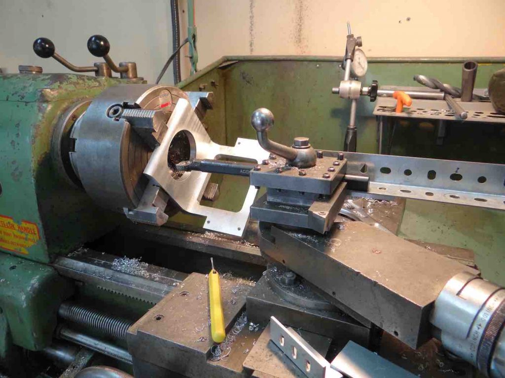
The last operation was to enlarge the 3 inch hole to about 3.5 inch, in order for the focuser tube (3 inch Paracorr in this case) to slide without interference with the focuser body:
At this point in the project I didn’t want to damage the right angle bracket by cutting too fast or too deep while enlarging the 3 inch hole. Indeed, the right angle bracket, held in the lathe by a four jaw chuck, could not as solidly be held in the chuck as before because there was now a cut in the bracket bottom, cut that weakened the bottom of the bracket but that was needed to nest the ball bearings. For this reason the cuts to enlarge the 3 inch hole were done at a very slow spindle speed (100 RPM) and with very light cuts (0.005 inches). It took over an hour to enlarge from 3 to about 3.5 inches in diameter.
To finish I remounted the angle bracket on the milling machine, used a hacksaw to cut off that bit of aluminium on the lip of the bracket, in front of the draw tube and I cleaned it up with an end mill. I then assembled the focuser to the bracket and adjusted the push-pull screws until the draw tube’s axis was parallel with the back of the bracket that attaches to the UTA of Mel’s 25 inch telescope.
Trials on Mel’s 25 inch Telescope
I shipped Mel Bartels’ 3 inch DSHC focuser to him about a week before the Oregon Star Party where the focuser was shown in public for the first time. When he tried the focuser with his 3 inch Paracorr Mel immediately noticed a slippage problem with the fine focuser assembly. I had used that soft copper pipe as a stand-in for the large Paracorr during prototyping and hadn’t noticed a real problem, though I had noticed it slipped once in a while. With the harder Paracorr, it didn’t work at all. That’s when I came up with the rectangular, rather than round, fine focus friction block. I machined one, shipped it to Mel who replaced the round delrin cylinder with the rectangular one and everything worked perfectly.
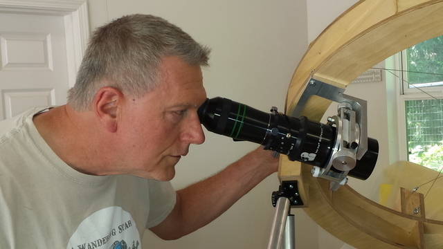
The picture above shows Mel “observing” with his 25 inch with the 3 inch focuser in place. As the photo shows, there is quite a stack of very expensive and heavy optical elements on the focuser. Although he will usually observe with the 2 inch Paracorr in the 2 inch Moonlite Crayford (the 3 inch DSHC focuser to be used mainly for astrophotography), he has used the 3 inch DSHC for observing and is quite pleased with it.
CONCLUSION
Inventing and building the first prototypes of the DSHC focuser was an enjoyable, but challenging project to undertake. Although I’m very happy with the result, I’m also aware that few people have the privilege of having access to their own, home machine shop like I do. So, as an additional challenge, I decided to design a simplified version which just about any amateur wood worker can build in his shop with simple tools. You will find a description of the simple DSHC plywood focuser here.