Assisted Lift Mechanism
Lifting the cover could make using this telescope shelter a chore unless some kind of assisted lift mechanism was used. When I first installed the cover, I found lifting it a bit difficult but I could cope with the force required. But I must admit it wasn’t fun. I measured the initial lift force, maximum when the cover is closed, at 75 pounds. I had given some thought to reducing this force early on in the project and gas springs seemed the most elegant way to proceed. I had purchased two 80 pound gas springs with about 10″ of stroke at a local store for about 10$ each, hoping they would provide enough lift energy. Unfortunately the combination of force and stroke of those two springs was a bit too small.
I calculated that two 100 pound gas springs with 16 inches of stroke would be much better, albeit still insufficient to lift the cover all the way up. On the other hand I didn’t want to go too much above 100 pounds. It’s a little scary to think the dammage a 200 or 250 pound gas spring could do to the telescope in such a small space should one of the end supports fail with the cover closed! So I ordered two 100 pound gas springs with 16 inches of stroke from McMaster Carr and installed those.
I started by machining and installing a lifting handle at the front of the cover in order to have a strong support to pull on.
First, here is a picture of the front of the cover as it now stands:
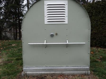
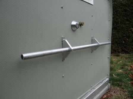
And a closeup of the cover’s front handle:
Positioning the gas springs relative to the hinge is what would determine the amount of force required to lift the cover throughout it’s full 90 degree rotation. I had to choose and balance how much force I wanted, at what angle. The springs were not long enough nor strong enough to cover the entire range (more on how to improve this later). Here are the efforts required to lift the cover with the help of the gas springs, in 10 degree increments:
0 degree (initial lift): 31 lbs
10 degree 26 lbs
20 degree 18 lbs
30 degree 8 lbs
40 degree -2 lbs
46 degree 25 lbs
50 degree 18 lbs
60 degree 7 lbs
70 degree 0
80 degree -7 lbs
90 degree (fully open):-18 lbs
So by placing the gas springs 22 inches away from the hinge I calculated that I would need 31 lbs of initial lift to begin raising the cover, instead of 75 lbs. A significant improvement! Then, that force would gradually diminish until the gas springs reached the end of their 16 inch long stroke, which occurs at approximately 45 degrees (halfway). At that point the cover is actually in balance and the gas springs just barely able to hold the cover in a partially opened position. To open further you then need to push on the cover without help from the gas springs. This takes approximately 25 lbs of force. As you approach the 70 degree neutral position (where the center of gravity of the cover is directly over the hinge) the force required to push gradually recedes to 0. You then need to hold the cover (pull back on it) as you gently bring it to rest on the two rubber stops described earlier.
I had to find a way to keep pushing the cover opened without the help of the gas springs and with them following along. Normally gas springs are attached at each end (like when opening a car’s hatchback). When you get to the end of the stroke the lift action is generaly finished. I could not do that with my setup.
What I did was to replace the fixed rod end fixture normally found on springe ends, with a 1 inch diameter phenolic ball (purchased from McMaster Carr). This ball glides in a slot which I milled out of the two 1.5 inch square tubings I had placed on each side of the floor, to fill the gap (see post #8). I haden’t planned on using those tubes for that purpose but they turned out perfect for this task. Not only would they guide the ball ends to their resting position when the cover is fully opened but they allowed the mechanism to operate under the floor. That way I would not trip over the guide mechanism during the night! I tought that was a pretty clever use of existing materials.
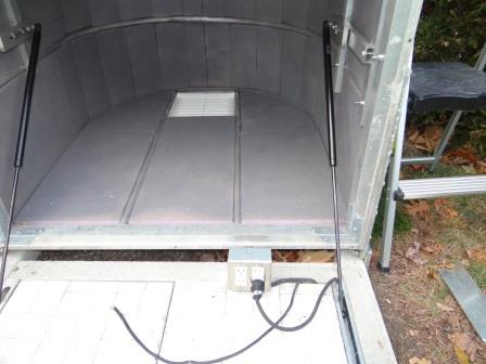
Here is a picture showing the two gas springs with the cover in a fully opened position:
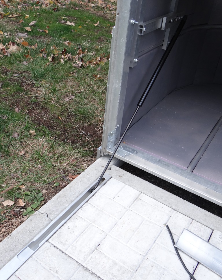
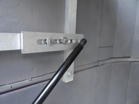
And a closeup of one of the two sliding cavities. When the cover is opened the balls retract back near the hinge. When assisting lift, they slide to that small aluminium block at the bottom of the picture to begin their compression action:
At the other end of the gas springs, the springs are attached to a small ball end which they snap into. To allow me to adjust for maximum use of the spring’s 16 inch stroke, I milled a long slot in a ½ thick aluminium flat bar, to which I attached the ball ends in which the gas springs snap into. The cover support structure on which all this is mounted was reinforced with four ¼ inch SS bolts that attach from the outside of the cover instead of depending on the small metal screws that attach the skin of the cover.
Here is a view of the cover in a fully opened position with the 20 inch in parking position, ready to retire for the night:

You will note the two gas springs fully retracted and out of the way, near the cover’s hinge. That way I don’t trip on them.
And a picture of the cover at a 45 degree angle. The bottom of the gas springs have now glided to their working position and are fully extended and holding the cover:
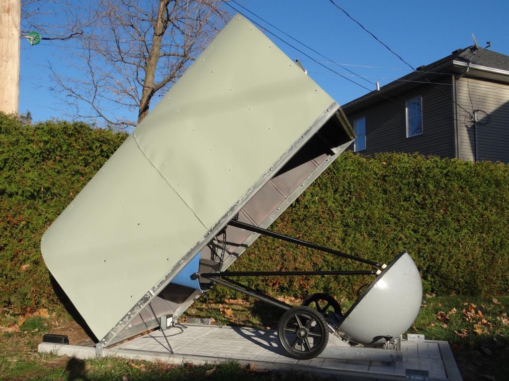
At that point I simply grab the bottom frame of the cover and gently pull the cover down, moving to the front to grab the handle and gently bring the cover to it’s resting and locked position. Gas springs are subject to a hysterisis force effect whereby they are stronger when being compressed and weaker when being extended. Pulling the cover down to the ground requires a significant reduction in force as compared to lifting (about a 10 pound difference).
SInce it’s getting cold working outside I will use the cover with this arrangement for now and see how I like it. However, I am considering adding a second set of gas springs next summer (those 80 pound ones I had initialy purchased) so as to make lifting even easier. Having 360 pound of lift force during initial lift would definetly be better than only 200 pounds. A possible scenario would be to move the 100 pound springs 18 inches away from the hinge (4 inches closer than they currently are). This would allow them to reach up to 60 degree position. Moving then to the 18 inch position would then free the 22 inch position to add the 80 pound springs. The lift force table per 10 degree increment would then look something like this:
0 degree (initial lift): 1 lbs
10 degree -5 lbs
20 degree -13 lbs
30 degree 13 lbs
40 degree 2 lbs
45 degree -5 lbs
50 degree -10 lbs
60 degree -24 lbs
70 degree 0
80 degree -7 lbs
90 degree (fully open):-18 lbs
In this scenario the cover would be almost in balanced position at opening and lift by itself up to about 25 degrees, where the 80 lbs springs would reach the end of their strokes. I would then need to inject about 13 pounds of force at the 30 degree cover angle, after which the cover would again start to rise by itself until 60 degrees, where the second pair of 100 lb springs would also reach the end of their strokes. A gentle push, followed by a retaining force would then be required to finish the rotation (as required with the current setup). Unlike the longer 100 pound springs, however, the 80 pound springs would have to rise with the cover and would stick out about 10 inches, 22 inches above the floor. I will only find out if this is a nuisance during use when I try it.