Electric Power
When building a telescope shelter, careful thought must be given to the electric power requirements. I don’t do imaging so my power requirements are low. Also, depending on how close or far the shelter is from a local power distribution can make this part of the project more expensive than anticipated!
The easiest way for me to provide power to the telescope shelter was through an underground power line connected to an electrical subpanel I have in my garden shed. I opted for a single, standard 110V, 15 amp circuit. When I built my garden shed a few years ago I brought 220V, 30 amps to it, just in case I would need it someday.
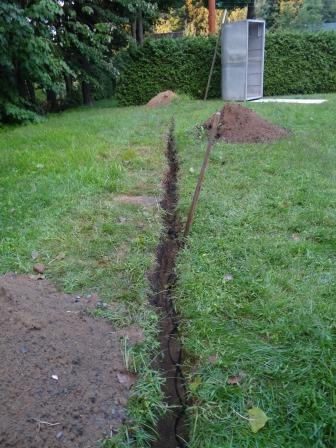
So I bought a 100 foot coil of caliber 14/3 cable of the NMWU type (for underground cable use) and started hand digging the 50 foot long, shovel wide trench to bury it. I looked into renting a trench digging machine capable of 24 inch deep trenches but it would have cost over 500$ for one day! Instead I decided I would take may time and dig a few feet every now and then while I worked on the shelter construction.
A funny thing happened while I was “taking my time”. This was in late spring and after a few weeks not working on the project I found a groundhog had decided that my then, 8 foot long trench, was a good start to his new home… which, of course, he elected to install right under the telescope shelter. I installed a cage with lots of vegetables and peanut butter and it took almost 5 days to catch him. I was actually lucky to see him entering the cage on a Saturday morning. Boy did he jump when the door slamed shut! I released him in a forest about 20 km away so he would not return.
Here is a picture of the the completed trench:
After drilling a 1¼” diameter hole in the foot thick cement foundation of the garden shed, I fed the power cable, along with another underground data cable I happened to have, through the hole and into the shed to the subpanel, where I connected it to a 15 amp breaker.
The Québec electrical code recommends burying cables to a depth of 20 to 24 inches, depending on whether they are protected in a steel pipe or not. I had dug to 18 inches and did not insert them in steel pipes so, I added 1″x6″ pressure treated wood planks on top of the power cable before backfilling.
The cable then enters the shelter from below the floor and foundation and emerges Inside, near the east hinge. I installed an aluminium bracket, screwed to the north foundation section on which I attached a 4″x4″ aluminium electrical box, through which the undeground cable was fed. This becomes the distribution box for power distribution throughout the small shelter. The underground cable first goes through a GFI electrical outlet. Downstream from this GFI outlet is a regular outlet. This provides four GFI protected plug receptacles to connect electrical material to. The plugs are all above ground so no water ending up on the floor can enter.
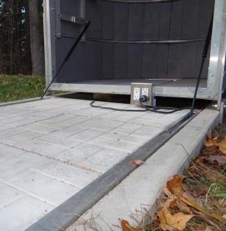
From the 4″ square electrical box, I currently distribute to two additional plug outlets.
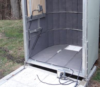
The first one, seen in this picture, brings power to the telescope’s dual axis tracking platform, to provide power to the R.A. and Declination drives, as well as the battery charger for the onboard gel cell battery, attached to the inside of the hemisphere, that feeds the dew heaters and eventual boundary layer fan:

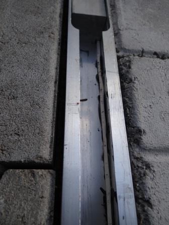
The interesting thing about this secondary plug outlet is that I’m feeding the power wire, from the 4″ electrical entrance box, through the east aluminium square extrusion which also doubles as the guiding track for the east gas spring. This way the wire is below the floor surface and there is no risk of tripping over it in the night. Here’s how I did it:
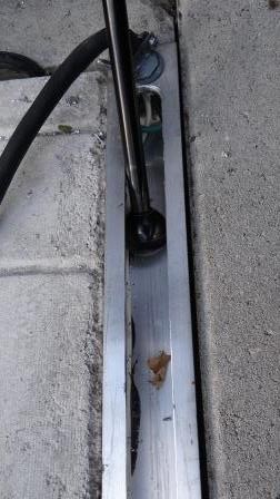
I purchased a short, caliber 14/3, flexible, power cable (with braided wire conductors). Attached a three prong plug at one end, which plugs into the 4″ square electrical entrance box. That cable then enters inside the 1.5″ square aluminium tube. I stripped about 24 inches off the rubber sheathing that surrounds the three isolated conductors. I cut the ground wire and attached it with a metal screw to the aluminium tube, thus grounding the entire square tube. I then glued the isolated neutral (white) and powered (black) wires to the inside bottom corners of the square aluminium tubes.
This allows the phenolic ball, screwed at the end of the east gas spring, to glide unobstructed between its resting position, when the cover is fully opened and the aluminium stopper plug, on which the gas spring pushes when holding the weight of the cover. I milled about 1/8″ from the the two bottom corners of the east stopper block to allow the wires to feed through to the inside of the square aluminium tube in which they run, all the way to the plug outlet, where they emerge to connect the double plug outlet that powers the telescope electrical requirements.
Here is a view of the gliding track for the gas spring ball end, showing the white neutral wire glued to one corner of the square tubing. The wire continues up to the aluminium stopper, the corners of which were milled out to let the wire go through to the other side.
A second, caliber 14/3 flexible power cable was attached to the bottom of the cover frame and brought up to the swing down desk which is attached to the inside of the cover (more on this desk in my next post). The second cable also plugs into the 4″ square electrical entrance box, flexing with the cover as it closes without interfering or getting squeezed between the cover and the floor.
At the desk end, the cable enters another electrical outlet box attached to the desktop. Three plugs are available on the desk.
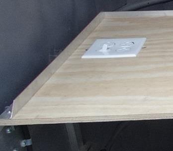
One of the plugs is switched and will turn on an 8 foot long, red LED lighting cable like those used for outside Christmas decorations. The red LED lighting cable will be attached to the inside top of the cover to supply a large amount of red light when needed. The other two desk plugs will be available to plug a small red desk lamp, a laptop computer, a heating box for the eyepieces…whatever makes observing convenient.
I am also considering adding one last plug on the cover frame so that when the cover is closed a small heater would be located near the floor (50W incandescent light bulb or some other low wattage heat source) which would help to keep the Relative Humidity inside the cover low enough to prevent condensation. Remember: the cover is insulated so I have to be careful not to overheat the inside of the cover on very cold nights (-20 or -30 deg C, for example), which would heat up the telescope and require a longer cool down period after opening. The idea is to find the balance between low R.H. and reasonable cool down time.