Building the Cover’s Frame
After completing the shelter’s foundation in early December of 2014, I moved to the warmth of the garage to assemble the cover. With my usual, unrealistic, optimism I was convinced construction of the cover would be swift and it would be finished in a few weeks… and out of the garage during the cold, snowy, winter months where the garage is most appreciated (we have a one car garage). Of course by April I was still working on it! 
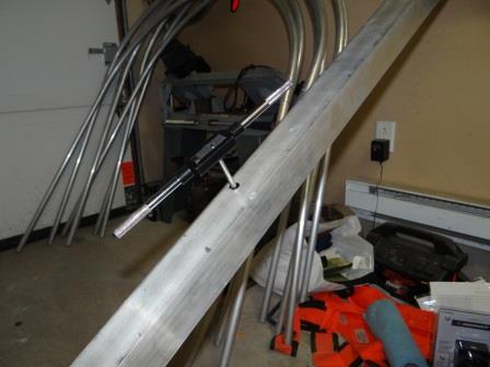
The first step in building the cover was to make the open frame that serves as the foundation for the rest of the cover. This bottom frame is also an extension of the moving hinge. It must be robust, lightweight and not subject to rusting since it is continuously on the ground when the cover is closed. I don’t have access to a welding machine so I chose an assembly method for the frame that could be assembled together with metal screws. In the following picture you can see one of the holes in the frame being tapped to receive a small plug which will locate and fix the rafters or “ribs” of the cage, visible in the background, which determine the shape of the cover.
I chose a square 2″x2″x 1/8″ thick tubular extrusion to make the bottom aluminium frame. Once assembled the frame is excatly 44″ x 93″ in size (exterior dimensions). The 44″ width was determined by the width of the Cement borders (39″) + twice the thickness of the borders (2″x3″=6″) less 1″ (½” on each side). The 93″ length was determined by the aluminium roll that used to serve as a 24 foot diameter, above ground swimming pool wall that I had on hand. This is a very old pool my parents installed 50 years ago and dismantled 20 years ago. When my father finally took the pool apart I asked him to keep the roll of aluminium that had served as the pool wall, with the intent of making an observatory dome with it. Instead of a dome, I ended up making this hinged shelter instead.
The pool wall was 48″ in height (today’s above ground pools are generaly 52″ high). Since I knew my telescope tube was about 80″ in length, I would need to place two widths of pool wall for a total of 96″. However I had the two 48″ aluminium skins overlap by at least 1″ . Also, I wanted the ends of the shelter to be recessed about 1″ at each end to leave and internal joint where I could apply caulking for waterproofness. So: 48″+48″”-1″-1″-1″=93″.
The base tubular frame was actually made just before assembling the foundation. I then used it as a template to determine where to dig (you can see it in the first pictures before excavation).
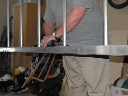
Since I could not weld the 2″x2″ tubular frame, I purchased some galvanized steel gusset plates normally used to reinforce the corners of wooden decks (at least I think that’s what they are used for). I drilled and screwed these gusset plates to the corners of the frame using metal screws. It makes a very strong frame. You can see two of these corner gusset reinforcement plates at the top of the frame in this picture (a simple corner brace on top and a more complex corner brace with sides at the bottom):
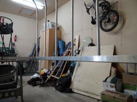
I determined how many wall frames I would install and their spacing. I decided on seven “ribs”. Those ribs are 1″ diameter x 1/16″ thick aluminium pipes, bent into shape. Although I made my own out of several tubes, it would be much easier to have the 7 ribs made by a machine shop equipped to bend these (and more accurate than the way I did mine). To locate these ribs, I machined 18 aluminium plugs with a machine nut in the center of the plug, screwing into a threaded hole in the 2″x2″ tubular framing. There are 14 plugs for the 7 ribs and two additional plugs at each end to attach the end walls.
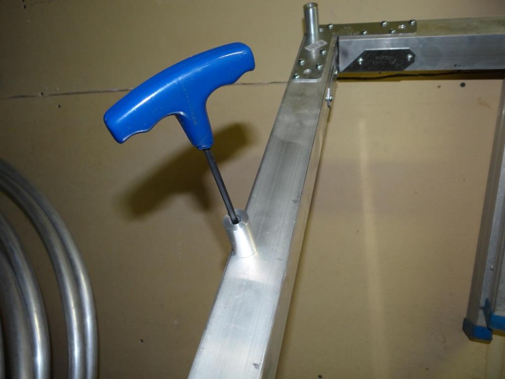
Although I made mine with aluminium (I have a machine shop at home), these could very well be made out of hardwood or, even better, delrin. The plugs are about 2″ high and the central bolt is recessed about halfway into the plug. You will see why in this picture:
The picture shows that bottom of the 1″ diameter tubes that serve as ribs, on which the skin of the cover is attached, cover the plug. One inch above the frame I drilled a horizontal hole and inserted a ¼” bolt to hold everything together. The ¼” bolt must, of course, be above the head of the bolt that attaches the plug to the frame. So enough room must be left on top to drill through. Once the skin is attached to the ribs these plugs become almost redundant but they are useful during assembly of the frame.