Double eyepiece turret system
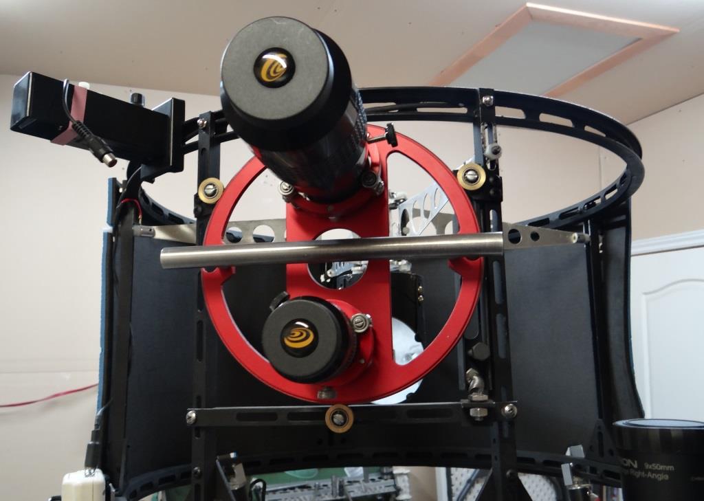
An important feature of this telescope is the double eyepiece turret system. The turret was designed to be as lightweight as possible so that no counterweights would be required under the mirror to maintain OTA balance. The two eyepiece holders are of the Helical Crayford design. This is the lightest Crayford eyepiece holder design available. It holds and focuses eyepieces without any play, just like a standard Crayford, but without the weight of focusing knobs and their support. The eyepiece is focused by rotating it. The axis of rotation of the small ball bearings on which the focusing tube rides are slightly angled (4 degrees in my eyepiece holders). By pushing the focusing tube tightly against the four bearings with Teflon cored bolts, the focusing tube moves up or down when it is rotated, following the angle of contact of the ball bearings.
The 2 inch eyepiece I chose for this telescope is the 20mm, 100 deg Apparent Field Of View (AFOV) eyepiece from Explore Scientific. It allows the observer to see 1 deg True Field Of View (TFOV) while producing an exit pupil of 5.2mm. A heavy, 2 inch wide field eyepiece must always be in the larger focuser to ensure tube balance. A Baader MPCC coma corrector is permanently screwed onto this eyepiece. Unlike the Televue Paracor, the Baader MPCC does not add any power so the focal ratio of f/3.9 is maintained and the field of view maximized.
The combined weight of the 2 inch eyepiece and coma corrector amount to almost 2.5 pounds! Without the 2 inch eyepiece permanently mounted on the telescope UTA, whenever I would switch from low power to a higher power eyepiece, the telescope would want to climb up due to the sudden imbalance. The nearer to the horizon the object, the harder it would be to hold the scope in position while changing eyepieces. Ball scopes are particularly sensitive to balance and it was essential that I solve this problem. That is why I designed, machined and installed this two eyepiece turret system.
As for the 1¼ inch eyepiece holder, it can be host to a number of higher power eyepieces, depending on objects to be observed and required magnification. Here again I called on ES eyepieces of 82 deg AFOV. Since the 20 inch is an F/3.9 equatorially guided instrument, a coma corrector is not absolutely necessary for eyepieces having focal lengths of 11mm and below, which is what I use during observing. In unguided dobsonians, not using a coma corrector is a problem since the object being observed is placed at one end of the field of view, a “coma infested” area, and left to drift through the central part of the field of view, where off axis aberations are minimal or non-existent. This is why fast dobsonians need good coma correctors at all times. Athough it is always better to use a coma corrector with an f/3.9 mirror, one can live without it with a tracking telescopes when observing at higher powers.
However for a wide field eyepiece it is preferable to have some kind of coma correction and the Baader MPCC provides more than enough for pleasant wide field views at a much lower cost (and weight) than the Paracor. The smaller eyepieces produce magnifications varying from 200x to 450x while providing a reasonable, 15mm eye relief. The 1¼ inch eyepieces weigh less than ½ pound so swapping them in and out does not significantly modify the center of gravity of the telescope.
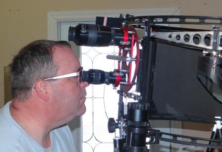
The turret diameter is 8 inches and the distance between the two eyepieces is 5 inches. This was deemed a minimum to prevent the large 2 inch eyepiece from interfering with the observer’s head when observing thru the smaller (and lower height) 1¼ inch eyepiece. Of course the eyepiece holders could have been mounted on a cone (like microscope objectives) but this would have made machining much more complicated. Here is a view showing the forehead clearance from the 2 inch eyepiece when observing in the 1¼ inch eyepiece:
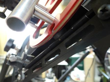
I can now switch from a wide field of view to a high power eyepiece in a second without losing the object position when the telescope is well balanced … and I maintain that balance. The red anodized aluminum turret rides on three small ball bearings in a V groove.
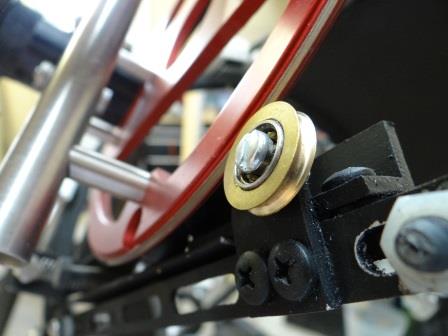
Here is a view of the bottom bearing with the 2 inch eyepiece holder in position:
And one of the two top bearings:
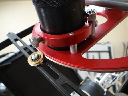
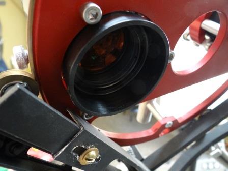
A small rolling, rubber ball is used as an indexer to locate the two eyepieces exactly on the optical axis. The rubber ball (picked up in the plumbing section of a hardware store) can be seen resting in one of the two indexing holes on the 8 inch disc, in the center of this photograph:
When turning the turret I first press on a button (the head of a ¼ inch bolt which you can see in the bottom left of the above picture, just in front of the spring) that swivels the rubber ball out of the way, freeing the turntable to rotate. The turntable can also be rotated without pressing on this button but I find it difficult to not move the tube slightly unless I push the rubber ball out of the way first. An aluminum handle is in place to have something to grab when pivoting the eyepieces. The turntable was machined in one pass on a milling machine to ensure both indexing holes and eyepiece tubes were exactly positioned.
When rotating the turret, the 2 inch eyepiece holder must always spin to the left side due to interference with the bracket holding the indexing rubber ball.
The above picture shows how one of the 2 inch helical crayford allen head bolts interferes with the indexing mechanism. In retrospect it would have been better to make the turntable an inch bigger in diameter to prevent this. However there is a limit to how large you want to make this wheel. I could also use recessed bolt heads but then the eyepiece holder barrel would interfere. The problem is easily solved by always having the smaller 1¼ inch holder swing on that side of the turntable since it clears the rubber indexing ball bracket support by quite a bit. By the way you will notice the brass bolt sticking out of a slot on the rubber ball bracket support. I use this to roughly center the eyepiece turret in front of the diagonal mirror.
The eyepiece turret works very well. It makes observing with this 20 inch ball scope a much more pleasant experience. It could also be used on dobsonian instruments or any other large Newtonian. One word of warning, though: The turret with the two eyepieces and helical crayford holders wheighs almost 5 pounds and rests only on those three small ball bearings. After the Friday evening optical judging at Stellafane in 2013, Jay Drew who coordinates the Stellafane judging activities, came up to the scope to take a peak through the instrument. I told him to go ahead and rotate the eyepiece turret. Suddenly the whole turret detached from the bearings and crashed to the ground! Poor Jay he felt really bad but it wasn’t his fault. The next morning I re-assembled the turret on its bearings and found that in my haste to get ready for Stellafane a few days before, I had stupidly forgot to retighten one of the small bolts that attach the bottom bearing beam to the frame. I was lucky for two reasons: 1- Had the turret been over the mirror, it would have been a disaster ! 2- Had the eyepiece turret been over a granite rock which Breezy Hill is covered with, there would have been dammage to the expensive eyepieces. Luckily it fell on a grass patch and there was no dammage.
I have since used the telescope many times and have not run into this problem again. Nevertheless I’m looking at attaching some kind of a security cable or spring that would prevent the turret from falling too far should one of the bearings fail or some other unpredictable accident (just like some people do by attaching a safety cord to a diagonal mirror which is glued to the holder, in case the glue fails).
Machining the Eyepiece Turret
Making an eyepiece turret requires some careful machining since both eyepiece holders must index to the exact same location in order for the optical axis of both eyepieces to be correctly aligned with the primary mirrors optical axis. I don’t know what an acceptable tolerance would be but when I was making this turret I aimed to be within +/- 0.002″. The method of fabrication I will now describe is not exatly the one I used, but an improved method I would use if I did this again. By the way a metal lathe and a milling machine are both required to make this kind of piece of equipment to the required accuracy.
My eyepiece turret is about 8½ inches in diameter. I started out with a 9″ x 9″ x ¼” thick aluminum plate which I clamped to the milling machine table. I then drilled two, ½ inch diameter holes and three 1 inch holes in the plate like this:
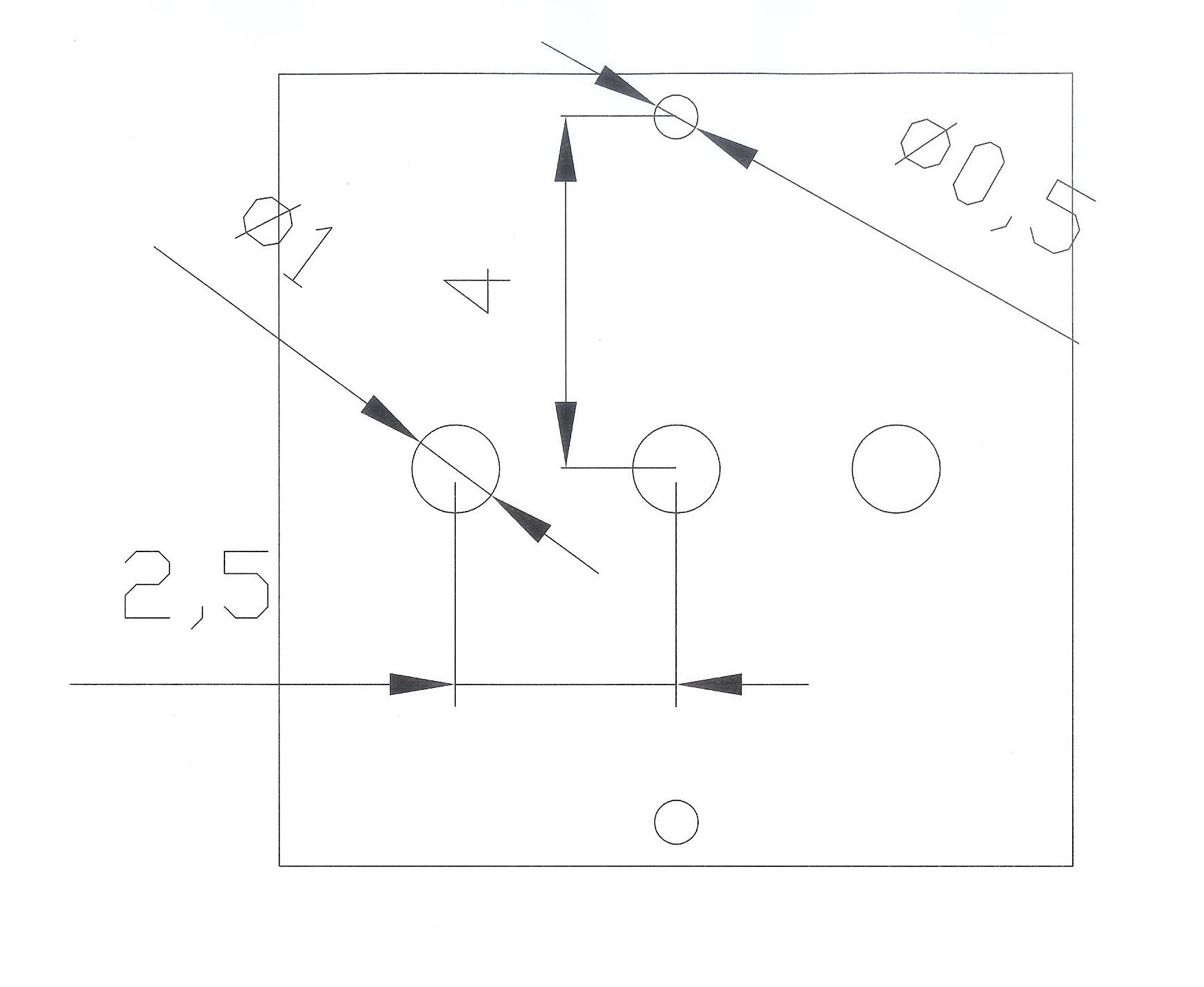
The hole positions were drilled with +/- 0.001″ accuracy. The ½ inch holes are the indexing holes are exactly 4 inches away from the center and exactly 90 deg away from the two outermost 1 inch holes where the eyepieces will be attached, when rotated around the center hole. As mentioned previously the eyepiece holes are exactly 5 inches apart from each other, 2½ inch from the center.
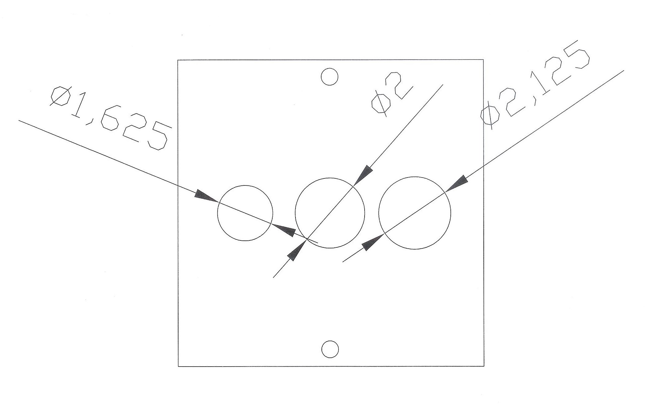
I then used a boring head to increase the diameter of the hole for the 1¼” and 2″ eyepiece holders. If I remember correctly they were 1.625″ and 2.125″ in diameter. The central 2″ diameter hole was also enlarged to lighten the weight:
I then removed the square plate from the milling table, cut away the corners and attached a short shaft to the center hole. I chucked this in the lathe and turned the plate down to 8½ ” in diameter. I then place the tool post at a 45 deg angle and machined the circumferential groove that engages in the three ball bearings that allow the turret to rotate. After this machining was over I removed the plate from the lathe chuck. I then returned the part on the milling table and proceeded to remove as much material as possible to make the plate lightweight without compromising rigidity. This was the result:

The last step is to accurately fix the Helical Crayford eyepiece holders to the plate. Most people will purchase these (you can get them from Kineoptics, see here) but I had all the material and tooling to make them and I’m an Amateur Telescope Maker so I like to do it myself when it’s reasonable to do so. I then turned two short plugs (about 1½ inches long) that would fit tightly in one or the other hole in the plate. The longest part of the plugs was then turned down to the exact diameter of the draw tube of the eyepiece holder. I then attached the ring that supports the angled ball bearings and tightened the teflon capped pressure screw around the plugs as much as possible:
The whole assembly was then moved into position under the appropriate drill bit and, without the motor running, the proper position was found where the drill bit would go through without dammaging the internal threads. The three holes for each eyepiece holder in the turret plate were then drilled through.
The last assembly step was to insert the three small tubed spacers of each eyepiece holder and cut/file them until each draw tube was perfectly perpendicular to the turret plate. To make sure they were perpendicular I would rack the draw tubes until they were flush with the underside of the turret plate and measure the difference in gap around the periphery with an indicator until I could no longer see any significant difference.
The whole assembly was then taken apart, the spacer tubes identified so I could put them back in the exact same configuration, and the parts sent for anodizing. The anodizing is important because thetwo, soft aluminium eyepiece draw tubes would be easily scratched by the angled ball bearings. I chose red just to add a little bit of colour to a more or less grey and black telescope. However it turns out this is also useful when collimating: I can see the red in the peephole when I’m doing prelimary collimation and I collimate until the red dissapears.
One last thing I did not realize when I machined that central hole in the plate: I could use this hole to hold a filter wheel which would index separately from the eyepiece indexing function. This is something I’m planning on adding in the near future but I must first shorten the 2″ eyepiece draw tube which sticks out about ¼ inch past the turret plate and would interfere with the future filter wheel.