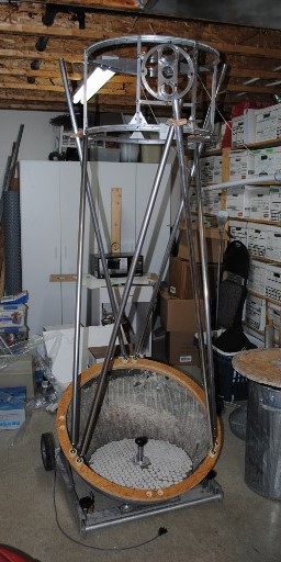
Truss tubes
The truss tubes are 1 inch diameter, 0.050 inch thick, black anodized aluminum tubes purchased from Moonlite telescope components. I initially tried 1 inch diameter, 0.030 inch thick aluminum shower curtain poles from the hardware store but found they were to springy to hold the UTA properly. Although I first assembled the UTA with 8 truss poles, I eventually chose to attach the UTA with 6 poles in order to minimize weight. This proved quite adequate and there is almost no vibration. Damping time of the OTA alone is less than 1 second when looking at Polaris at 420x magnification and I don’t think it’s coming from the OTA but rather from the tracking platform .
Determining the final pole lengths was a frustrating exercise. Because of the slanted reinforcement ring on top of the hemisphere and no point of reference as to where the optical axis was, I first built a temporary jig to hold and adjust the UTA. I then did my best to adjust it until I thought I was in the correct location. In order not to accidently dammage the pyrex mirror, I used the 20 inch diameter, 2 inch thick cement grinding tool as ballast.
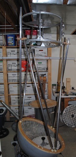
For this jig, I used the aluminum shower curtain poles and mounted them on temporary, articulated wooden tube holders.
I adjusted the distance between the center of the primary and secondary mirrors, taking the 78 inch focal length into consideration and substracting 14 inch for the side focal plane position. I then cut the shower curtain poles two inches longer than necessary and assembled the telescope. When everything was ready I replaced the cement grinding tool with the still un-aluminized, 20 inch mirror. I pointed the telescope to the sun to determine the focus position more accurately and re-adjusted the truss tube lengths using the temporary steel angle brackets between the UTA and the top of the truss tubes.
Even though I took all these precautions before cutting the more expensive Moonlite truss tubes, I still ended up cutting them about 1.5 inches too short (two of the truss tubes had to be shimmed with 1 inch aluminum spacers). These first Moonlite truss tubes were 1¼ inch in diameter. After reading Albert Highe’s book and using his equations for calculating deformation caused by both bending and tube offset, I realized that 1 inch diameter tubes would work just as well and would help improve OTA weight balance. Since four of the tubes were too short anyway, I bought a complete set of 1 inch tubes and that’s what I have on there now.
The bottom of the tubes are attached to the hemisphere reinforcement ring using a 1 inch chrome plated brass ball joint normally used to hold shower heads. These metallic joints are now harder to find in hardware stores (they were purchased in the late ‘90’s whereas most are now made of plastic). An alternative would be to purchase 1 inch aluminum or stainless steel ball joints available from McMaster Carr. Another method would be to use Australian ATM Jonathan Pogson’s approach with Heim joints, described in this Cloudy Nights thread.
The center of the ball is threaded to take a 5/16 inch diameter, 3 inch long stainless steel threaded rod. This rod threads into an aluminum plug attached to the end of each truss tube and locked in place with a nut. This assembly allows approximately a ± 1 inch adjustment of the truss lengths. This adjustment is important to allow centering of the UTA around the optical axis and to fine tune the focus plane position of the double focuser assembly.
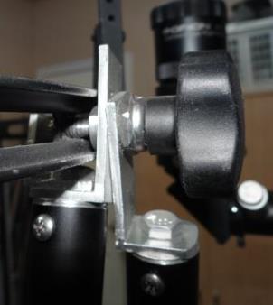
The balls are secured in a socket that is attached to the hemisphere’s reinforcement ring. A large plastic locking ring that came with the shower head assembly covers the edge of the ball and screws into the socket. Due to the strongly slanted reinforcement ring, the angle on some of the truss tubes is more than 45 degrees to the ring’s surface. This large angle excluded using conventional ball and socket arrangements found on amateur telescopes (like Monnlite’s). A smaller diameter stem (threaded rod) was necessary to allow for more angle. The following picture shows the ball and socket arrangement.

The white plastic sockets have since been replaced with aluminium ones when I discovered micro-cracks in them. The weight of the entire UTA rests on these six sockets. They have to be robust.
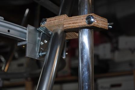
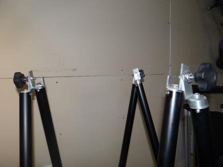
The upper end of the truss tubes are permanently attached together in pairs, using 1/8 inch thick aluminum brackets. When the truss tubes are disassembled they fold on top of each other. I plan on making some kind of pouch to hold and protect the three pairs of poles when in transit. The attached assembly is made using ½ inch aluminum bolts purchased from McMaster Carr. The hexagonal bolt head was turned to a diameter small enough to fit between the rim of the lower bicycle rim of the UTA. The bolt head was also machined to a thickness of about 1/8 inch, also to nest within the gap between the rim walls. Two flats were then milled to provide a gripping surface when assembling the bolt to the aluminum angles at the top of each truss tubes, with a nylon locknut. The following sketch and picture shows the various components of this UTA attachement bracket:
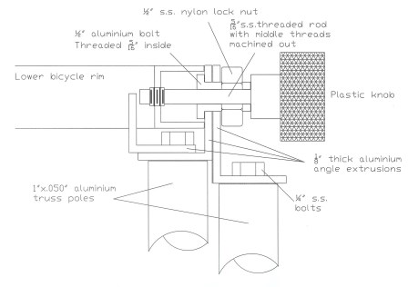
The center of the ½ inch aluminum bolts are drilled and tapped to take a 5/16 inch stainless steel bolt. The threads in the center of the bolt were machined out and the bolt was then permanently screwed into a plastic knob. When the knob is attached to the center of the ½ inch aluminum bolt, it remains captive after removal of the truss tubes.
Here is the assembly procedure when I arrive at an observing site. All this takes less than 2 minutes and requires no tools.
First, the three truss pairs are attached to the six sockets located on the hemispheres’ reinforcement ring.
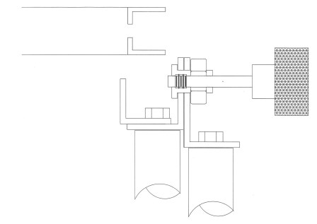
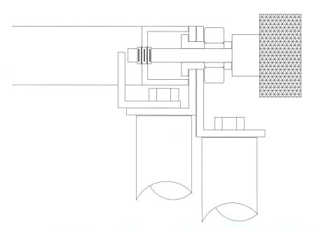
Then, the empty UTA (no eyepieces, no finderscopes and no heater control) is lifted up with both hands and aligned with the three waiting aluminum brackets at the top. Unlike most truss tubed amateur telescopes, I don’t need to hold the empty UTA with one hand while I push the truss pairs in position or have to bolt or screw someting with the other hand. Instead, the top of each truss pairs ends with a small fork, or hook. I “grab”, one by one, each of these hooks with the lower bicycle rim and pull or push the truss pairs until they are in the right position. All this, of course, is done with both feet on the ground. Here is a sketch showing the bottom bicycle rim above one of these forks, just before it is lowered on the truss attachement bracket:
When the three pairs of trusses are at the right position, I lower the empty UTA onto the three bolt heads in the bottom of the “fork tops”, like this:
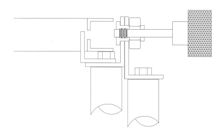
Finally, I screw the plastic knobs and their 5/16 inch stainless steel bolts in until they tightly attach to threaded holes in the bottom UTA bicycle rim.
The large knobs, both at the top and bottom of the truss tubes, means no tools are required to assemble the OTA. Assembly/dissassembly can easily be accomplished with gloved hands.
To maintain collimation the three paired truss assemblies must always be attached to the UTA in the same positions when the telescope is assembled. Each of the pairs measure approximately 42 inches for the short pair opposite the eyepiece turret and 52 inches for the two pairs on either side of the turret. I eventually plan on numbering them, but with practice, I’ve come to be able to tell them apart. With this setup, collimation is rarely far off, even after a long trip with the telescope disassembled in the car. If collimation is off, it’s generally because I mixed up the trusses during assembly