The dual Axis, multi-latitude tracking platform is an integral part of my 20 inch ball scope. This platform evolved from the single axis platform I invented in the mid-90’s. See here for a detailed description of how this invention came into being and how the dual axis platform works. Although I first published this novel platform design in the mid-90’s, very few have been built and even fewer dual axis were made. At the moment of writing this I believe this is the largest tracking ball scope in the world.
Overall view of the platform
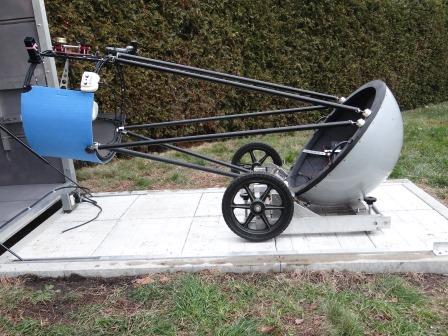
First, here is an overall view of the platform.
First with the hemispherical tube in place as seen from the west:
e
And a closeup view from the top when the telescope is looking north and is in it’s storage position :
Static Safety Supports
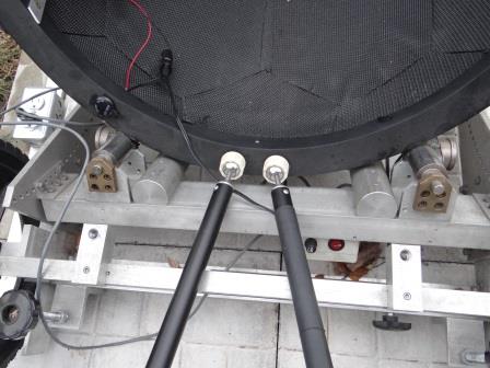
You will notice in the above picture that the upper ring of the hemisphere is barely touching the two drive rollers. Just to the side of each rollers are two supports that hold a small steel ball that serve as static (non-driving) supports. Here is a closeup view from the side:
These static supports serve two purposes. First, they allow the telescope to point low in the polar region. Without these supports the telescope would be limited to about 40 degree pointing altitude (with them: 15 to 20 degrees). The second reason for these supports is to “catch” the tube if it falls off it’s drive rollers. There is a safety bumper surrounding most of the upper rim of the hemisphere, which prevents accidental movement off the drive rollers (including the idler roller). Indeed, the hemisphere that serves as the base of the tube was deliberatelyf made assymetric to significantly reduce the weight of the instrument, as described here.
Without the edge bumper, the “narrow” part of the hemisphere could inadvertently fall off one of it’s three supports. However, about 1/3 of the hemisphere deliberately does not have that bumper, to allow the “wider” part of the hemispherical tube bottom to reach low in the circumpolar area of the sky.
Although I made the static ball supports very stubby, they are cantilevered and there is more vibration than usual when the hemispherical tube rests on them. The hemispherical tube moves almost seamlessly to this position when required and, of course, the telescope is not driven since it is no longer in contact with the drive rollers. There is no switch to turn on or adjustments to do for the transfer to occur. When finished, the telescope is simply rotated back up on its drive rollers and tracked observations can resume in the rest of the sky.
You will notice also on this picture how little space there is between the hemisphere and the support structure and drive rollers. All elements of the equatorial platform had to be carefully layed out and machined to prevent interference, at any latitude the telescope is likely to operate from.
Drive rollers
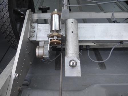
Here is a view of the platform with the OTA removed:
![]()
And a few pictures showing the Right Ascenscion drive beam with it’s two driven rollers, as well as the static supports:
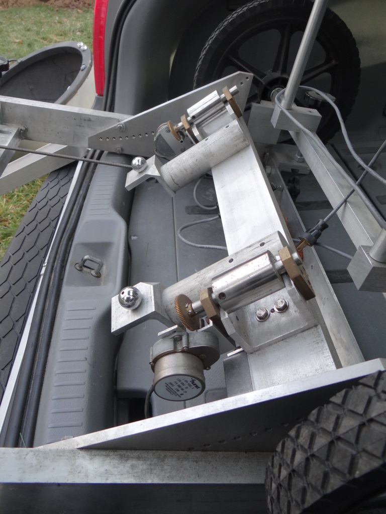
The two 1½ inch diameter drive rollers are very hard and wear resistant, high chrome content 5054 steel used for linear bearing shafts. They are hollow shafts and I interference pressed a 1 inch diameter soft aluminum shaft in their center to be able to insert a setscrew (it is extremely difficult to machine this type of steel). The aluminum cores were also drilled with a ½ inch center hole. The setscrew tightens around a ½ inch steel shaft riding on bronze bushings. They are driven by a 1 RPM synchronous motor which meshes with a 72 tooth worm gear to obtain the correct sideral rate for the large, 30 inch diameter hemisphere. The advantage of using high chrome steel is that the surface will not wear out when spinning the tube across the sky. Also, the friction characteristics will not change with temperature (plastic or rubber driving rollers would not act the same way at very cold and very hot ambient temperatures).
Here are two views of one of the driven rollers. The first picture shows the driven roller alongside the static support:
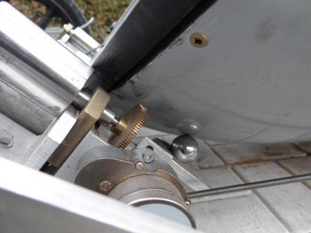
And a closeup of the drive roller itself:
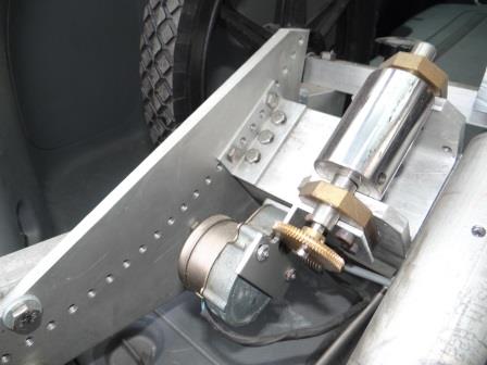
The above picture shows the 1 RPM motor and worm gear as well as the side indexing plate with the series of holes that allow the latitude to be adjusted to the location where the instrument is used. Unlike a conventional tracking platform like a Poncet, the holes allow an adjustment between about 15 and 55 degree latitude.The drive motors are also reversible, the platform can be used almost anywhere in the world (except near the equator), in either the Northern or Southern hemisphere.
Latitude is adjustable in 2º increments by unbolting four bolts that hold the drive roller support beam and moving the beam along an arc of carefully positioned threaded holes milled into the two side plates. Accurate latitude adjustment is then completed using the leveling legs, as required.
Idler roller
The entire OTA rests on only three points: the two drive rollers and a third, undriven idler roller.
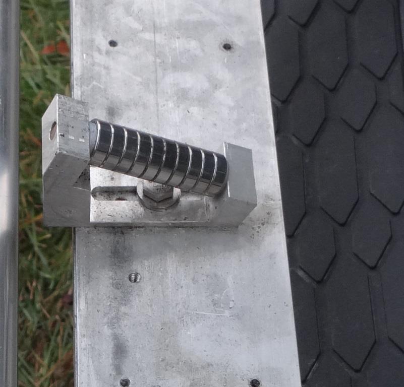
I made the idler roller by inserting 8 small ball bearings of the type found on the tips of router bits. I did not have much space available and wanted to maintain the OTA as low to the ground as possible. I calculated the angle the roller needed so as to position the hemisphere at the center of the roller and milled the support bracket accordingly.
The idler roller is mounted on a long aluminium plate, which I call the tangent arm.
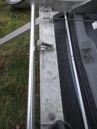 This arm has a pivot at one end (bolt at bottom of the picture) and a slot at the other end, held by a bolt and locknut. A long 1/4 inch stainless steel threaded rod is attached to the tangent arm, near the slot (at top of picture). Here is a closeup view:
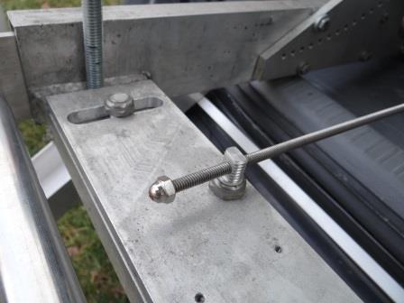
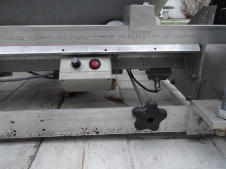
At the other end of the threaded rod, under the RA drive motors, there is currently a plastic knob:
A the moment the tangent arm is not motorized but it soon will be. I have the gears and the motor, I just haven’t had time to install it. In theory the telescope could be used for astrophotography when objects are crossing near the meridian (+or – 15 degrees). Further east or west, as with all dual axis equatorial platforms, there is field rotation.
I’ve experienced a bit with this tangent arm, just having someone rotate the knob while I observe. It works but the movement is not smooth, especially when the idler roller is moving away from the RA drive rollers. The problem is that even though the OTA is putting a sideways pressure on the idler roller, the tangent arm movement sometimes sticks as it moves back, releasing the movement in a sudden fashion as the backlash in the threaded rod is picked up. I have bought a long stainless steel spring which will surround the threaded rod and apply pressure on the tangent arm, never letting the backlash manifest itself.
Leveling Legs and Latitude Adjustment
The leveling legs are rarely used but are available if required. Accurate polar aiming is not required for visual observations but, should the telescope ever be used for astrophotography, the leveling legs provide an accurate means of aiming the drive rollers with the pole. The adjustable leveling legs are equipped with removable Delrin feet which are clipped on when required. When not in use, and during transportation, the adjustable legs are fully retracted and the feet are removed.
Another modification I plan is to add a wheel lock for the two 14 inch transportation wheels when I use the telescope for visual observations only.