Conical Mirror Deformation
How much does a conical mirror deform under it’s own weight when it’s supported only at its center and what effect does it have on optical quality? This is not an easy question to answer. With standard thickness mirrors one can use PLOP and Cruxis mirror edge calculator because someone has already done the mathematical approximations and assumptions. Not quite the case for a non standard shape like this.
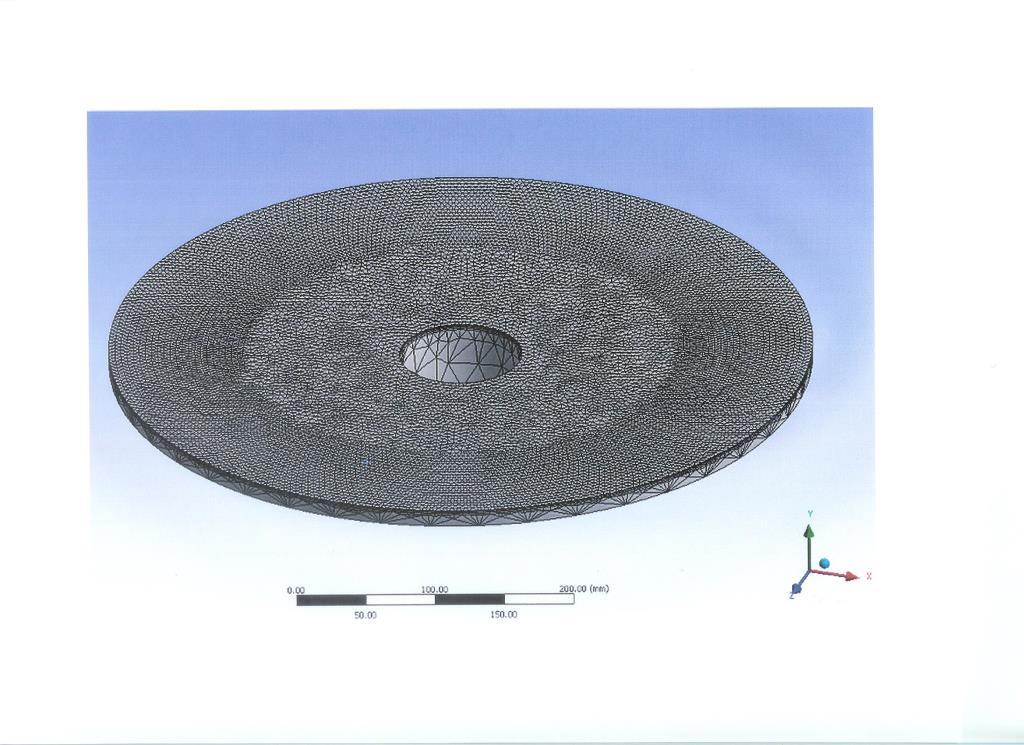
To get an idea of the microscopic shape changes one must use Finite Element Analysis (FEA) techniques, where the mechanical properties of a material and its shape are dissected into very small individual micro-components which are then analyzed by a computer while applying pressures to the component being studied. I haven’t done FEA since engineering school so my skills in this were pretty much non existent. However I have a work colleague who does this on a regular basis with components much more complex than my simple piece of glass. I provided him with an AutoCAD drawing and the physical properties of Pyrex and he did a mesh reduction that looked like this:
He then submitted the conical blank to several positions (in a virtual fashion) and looked at how much the glass was bending under its own weight. As expected, the worst case position was a horizontal blank (looking at zenith). Here is what he found:
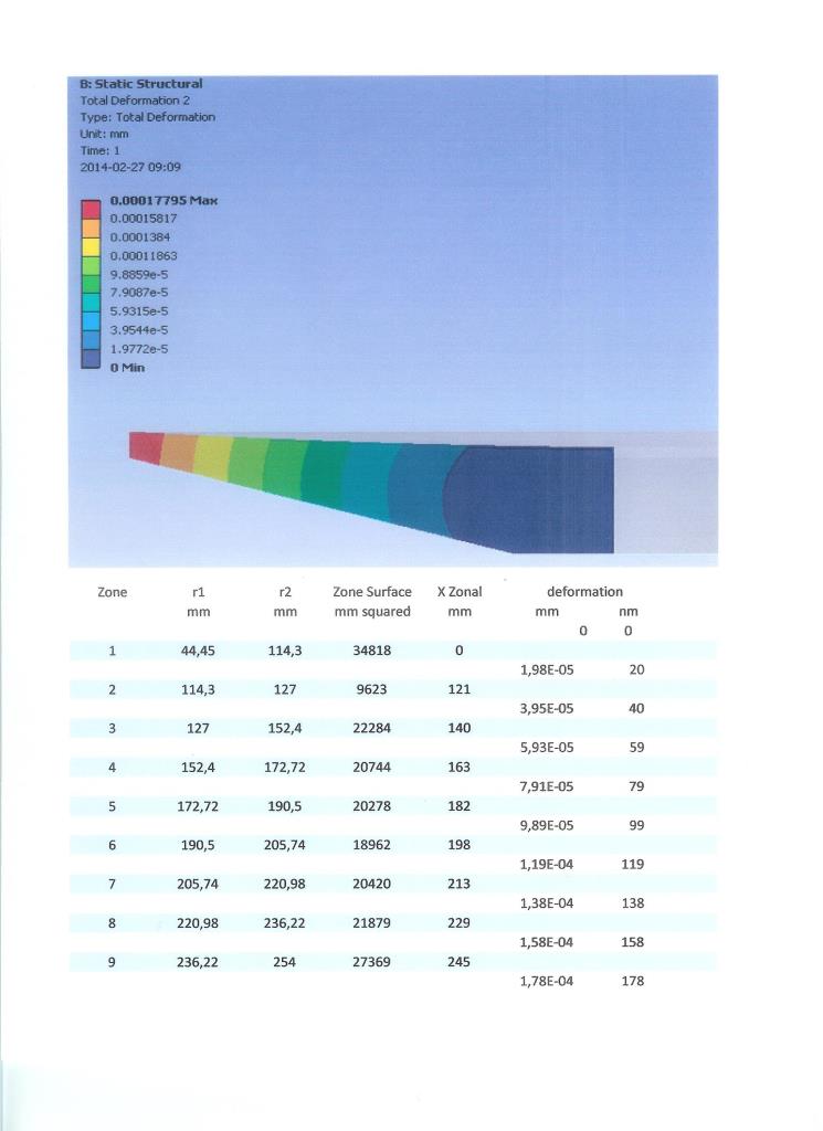
The last column below the half-blank image shows the peak to valley deformations from center (zone 1) to edge (zone 9). This indicates a maximum of 178 nanometers of deformation, or about 1/3 wavelength at a wavelength of 550 nm. This is a lot. However, that does not tell the whole story. Back in 2007 the deformation of conical mirrors was discussed in Cloudy Nights in this ATM forum thread: http://www.cloudynig…nded/sb/7/o/all and this one as well: http://www.cloudynig…ed/sb/7/o/all.�
In the first thread, Robert Houdart (Cruxis) did a calculation on Mike Jone’s 24 inch conical blank and found:
Before refocus: surface error RMS 107 nm (1/5 wave), P-V 380 nm (2/3 wave)
With refocus: surface error RMS 10 nm (1/55 wave), P-V 40 nm (1/14 wave)
Mike’s blank has a similar shape proportion to my 20 inch so I am confident my blank is not seriously affected by mechanical deformation of its surface when supported only by the center. But I wasn’t sure.
Luckily, a discussion on conical mirror deformations was started by Cloudy Night contributor Ckh in this thread (thank you for that!). Calculations showed the 20 inch conical mirror, when deforming under it’s own weight, seems to be deforming from one parabola to a new parabola. I redid the calculations because I had initialy made some mistakes measuring the approximate positions of the zonal changes on the FEA graph. Taking into account the more correct positions of these zonal changes, here is what I came up with:
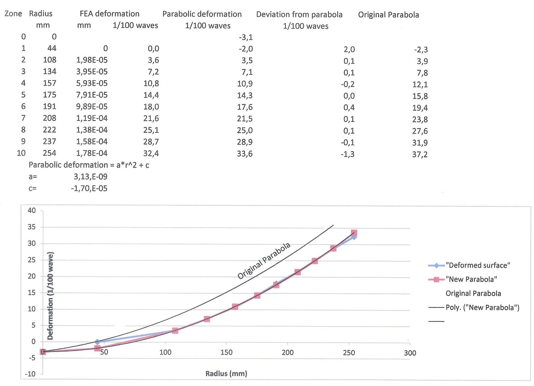
After correcting the zone change positions along the X axis, I manually re-adjusted the values of “a” and “c” to find the best possible parabola to fit the new Y coordinates of the surface after it slumps under its own weight (blue line). The match with this new parabola (red line) is remarkable! We see that the surface located over the 7 inch diameter flat bottom does not quite follow the new parabolic shape, but not by much (0.02 wave or 11 nm). There is also a very slight deviation at the very edge (0.013 waves or 7 nm) but I suspect this is just an artifact caused by the FEA software when it approaches a discontinuity like the edge of the glass. Everywhere else the new parabola matches like a glove. So the total p-v deviation from a perfect parabolic shape is 0.033 wave or 18 nm. I haven’t calculated the overall RMS error but it would be very small.
I also did not discuss the effect of a centrally supported mirror when it is in other positions than horizontal. However, I do have the FEA analysis at 45 deg and vertical inclination (looking at the horizon) and the deformations are considerably less than the worst case position, which is the horizontal discussed above.
I will finish this discussion with the conclusions I have come to, thanks to Ckh and Vla’s calculations in the other thread and my experience working this type of glass shape:
- A perfectly parabolized conical mirror with similar proportions to my 20 inch blank will slump under its own weight to another, perfect parabola when its surface is moved from a vertical to a horizontal position. There are obviously limits to this characteristic (the mirror must be sufficiently thick in the center and thin at the edge, for example) and a full study of various conical shapes would have to be undertaken to map the limits.
- Supporting such a mirror is very simple, needing only a central post to support the glass. The use of an adjustable Stewart Platform truss tube structure is all that would be needed for collimation. No need for floatation supports, slings or other edge supports. If the truss tubes are well made, the mirror will rarely, if ever, need to be re-collimated except when it is removed for cleaning.
- The fact that the glass is “suspended” on the simple support makes ventilating the mirror very simple.
- The fact that the edge is thin makes thermal stabilization faster.
- The fact that the edge is thin makes the glass lighter.
- I’ve shown, here, that grinding and polishing a conical blank is simple when there is a hole in the center. Parabolizing and testing is also simplified by gluing the glass with pitch to a central support.
- The one disadvantage to a perforated primary mirror is that conventional laser collimation tools cannot be used. Collimation must be done by observing a star.