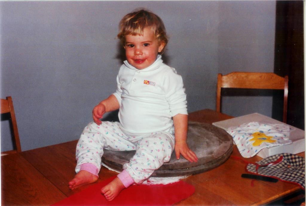
The 20″ telescope project began after I located a suitable slab of glass. In 1990 I saw a classified ad in Sky and Telescope by Dick Nelson, owner of the Optical Crafstman telescope making company. He was going out of business and getting rid of two 20 inch, conical pyrex blanks. I got in touch with him and obtained one of them for $500. The blank was a rough, cast piece of glass that would require a lot of work even before grinding could begin. The blank was almost 2½ inches thick over the central 7 inch diameter portion and then tapered out to about 1 inch at the edge. It weighed approximately 50 pounds. The front surface was far from flat and had “ripples” of glass with variations in thickness of up to 0.1 inch. The diameter varied from 20¼ to 20¾ inches. This picture (with permission from the now grown up lady!) shows the eldest of my daughters sitting on the just received blank:
I had read with interest Donald Dilworth’s relay lens article in the Nov-Dec 1977 issues of Sky and Telescope in which Dilworth had made his 16 inch blank lighter by tapering the edge of a full thickness blank to create a conical blank and supporting it through a central perforation. I thought this was a clever way of both reducing the weight of the glass and simplifying the mirror mounting. In his two part article Dilworth explained how he had used grinding wheels to grind away the excess glass and produce his tapered mirror. I would do the same by grinding away the back of my already tapered glass blank to further reduce the edge thickness from 1” to ½” and I would trepan a 3½” hole for central support. Reducing the weight and thinning the blank as much as possible was important for two reasons: weight reduction would prevent the hemisphere’s skin, in which the mirror would be supported, from buckling or bending (creating vibration). The mirror had to be heavy enough to balance the UTA but light enough not to put higher than necessary stress on the hemisphere. The 30 inch diameter of the hemisphere had been calculated to balance everything out (see here for more details). One of the design goals was to have a 75 pound OTA, a formidable objective. A lightweight mirror blank was central to attaining this goal. After all the work described below, the 20 inch conical mirror blank ended up weighing 32 pounds.
The other reason for thining the glass was to allow it to cool as quickly as possible without resorting to fans blowing from the back. Indeed, the hemisperical ball’s skin could not be perforated to allow vent holes if it was to be used with the tracking platform I had just invented (I had long discussions with Mag1 Instrument founder Peter Smitka on this at the time this decision was being contemplated). Almost 70 % of the light gathering surface of the pyrex mirror is less than an inch thick and, the glass is suspended, with no mirror cell touching it, favoring natural convection with the surrounding air.
Preparing the blank for rough grinding
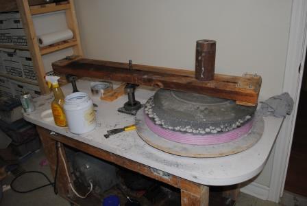
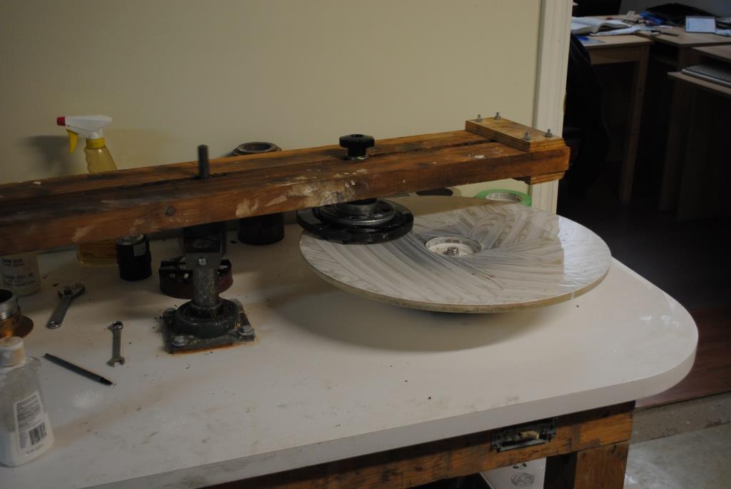
To do these operations I built a grinding machine which would be used throughout the project. My grinding machine, shown in these pictures, was based on Dilworth’s grinding machine seen in the Nov-Dec 1977 issue of S&T:
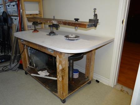
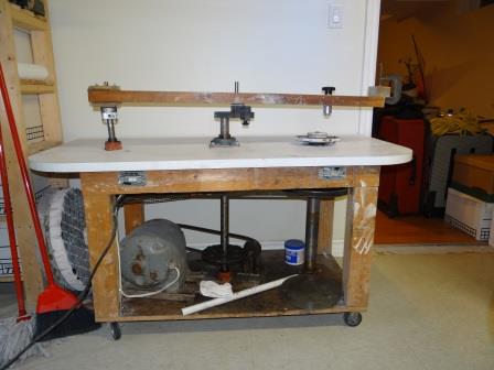
The grinding machine has three spindles. The right spindle is the one on which the mirror is mounted. It spins at approximately 2 RPM. The central spindle controls the back and forth movement of the grinding/polishing tool. It’s stroke can be adjusted by sliding the crankset pin radially. The left spindle can also be used to induce an offset movement but I rarely used it. The pin stayed centered most of the time. In addition, the long push arm holds the pin that pushes the tool or mirror blank and it can be adjusted lengthwise to adjust for tool offset. A 2 HP motor provides more than enough power.
Before grinding the back of the blank to lighten it up, I paid a tombstone maker a visit and asked his help to remove glass to roughly “work in” the F/3.8 curve I was going to need for the mirror (ended up at f/3.9). Using sandblasting techniques and a 24 inch long template with the correct radius, he was able to “generate” the rough radius of curvature after only a few minutes of work. Using a diamond grinding wheel I also cut away the excess glass on the edge to regulate the diameter to a circular 20¼ inch dimension. If I had to do this again, I would use the curve generation device recently described by Chriske on CN: see here.
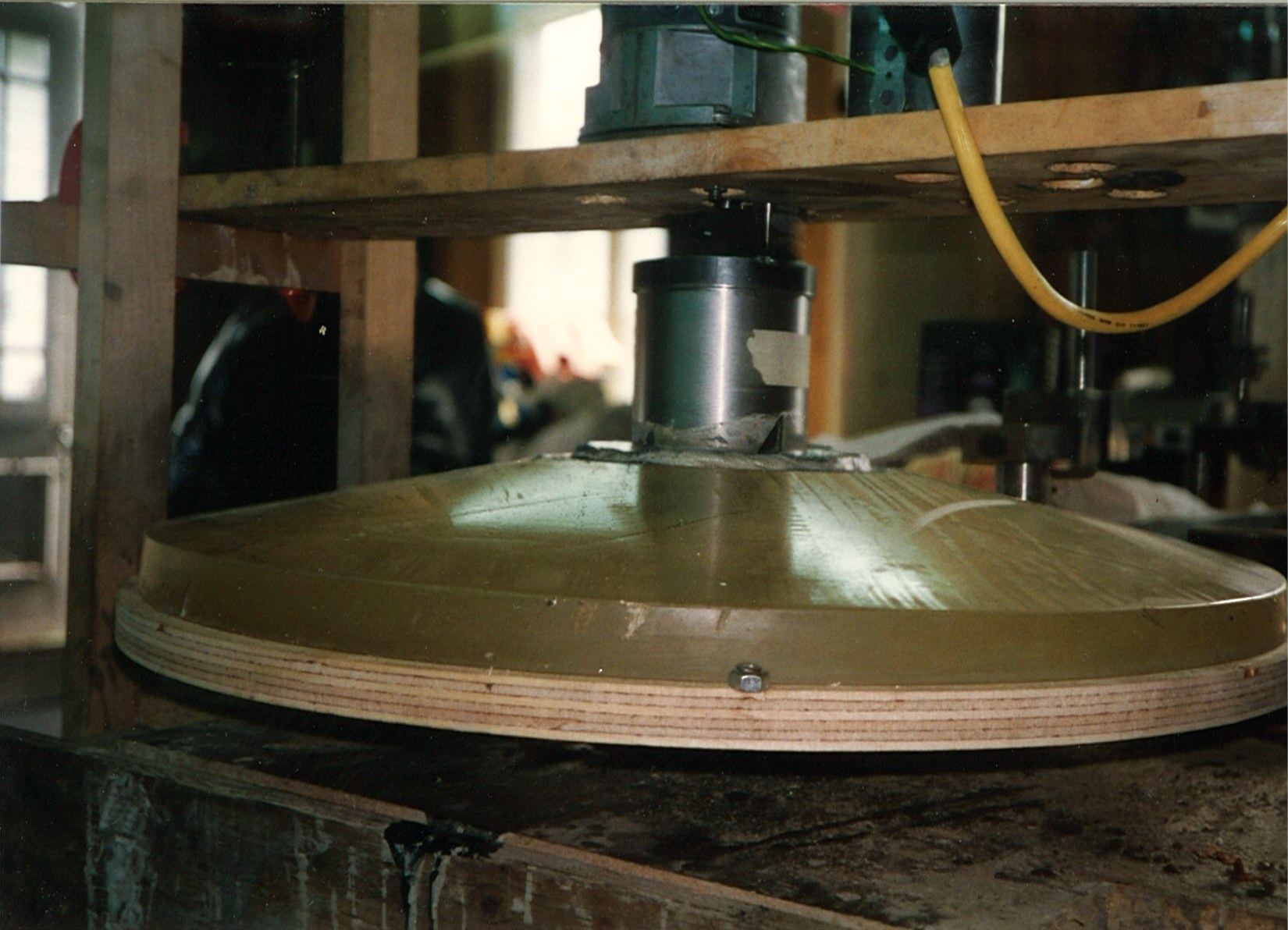
Glass from the back end of the blank was then removed by mounting a motor with a spinning grinding wheel attached to the arbor, just like in the Dilworth article. The motor was mounted on an angled linear guide. The blank would slowly rotate (2 RPM) while I would move the motor from edge to center at an angle, increasing the taper and thinning the edge down to ½ inch.
A word of caution: use proper eye, ear and respiratory protection if you ever attempt this! In normal grinding, a wet slurry of carborandum is slowly used to grind out the curve and there are no health risks. However, in a mechanized operation like this, carborandum dust and glass quickly become airborne and can get into our branchi and lungs. Exposure to these aerosols could cause emphysema and/or lung cancer.
Trepaning
The blank was then mounted on a threaded pipe and a 3.5 inch steel trepanning tool, attached to a rotating motor arbor (≈150 RPM), was then used to “drill” a hole through the center by feeding #60 carborandum and water.
As the trepanning tool spun, the blank, mounted on a non rotating table attached to a long, threaded 2 inch pipe, was slowly moved upwards towards the tool. It took several hours to pierce through the center of the 2½ inch thick glass blank. This picture shows the blank when it still had a 1 inch thick edge.
Final Curve Generation before Rough Grinding
Rough grinding the f/3.9 curve was first done with a spinning a 4 inch, followed by an 8 inch cast iron tool (a cast iron skillet with the handle cut off and slots milled in the sides). The tool was set at an angle in relation to the slowly rotating mirror blank surface, below and offset. This picture shows the 4 inch tool working the glass:

This is a technique used by professional opticians, normally in conjunction with large diamond wheel tools, to quickly generate the desired curve (“Blanchard curve generation”). I did not have a diamond wheel but, nevertheless, with this method I was quickly able to grind away the rough curve that had been initiated by the tombstone maker.
Conventional Grinding
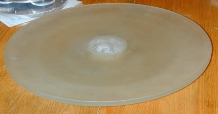
After generating the f/3.9 curve using the methods described above, and thinning the edge of the blank to ½ inch, the 32 pound, 20 inch pyrex mirror blank was ready for conventional rough grinding with a full sized tool. Here is what the glass looked like just before conventional grinding:
Two, 2-inch thick and 20 inch diameter tools were then cast out of a Portland cement mix (containing no stones). I used the rough f/3.9 curve of the blank surface as a mold. One of the tools would be used to support ceramic tiles for grinding; the other cast as the pitch lap. During casting of the cement tools, a 3.5 inch diameter plastic drainage tube was inserted at the center of the tools to create a hole, corresponding to the hole in the center of the glass blank. This hole would not be covered with any ceramic tiles or pitch, to match the corresponding absence of glass in the glass blank. The holes would also provide a location to fix the cement tools during grinding/polishing.
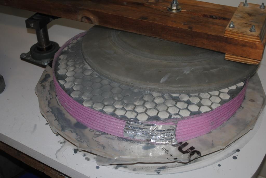
Unglazed ceramic tiles, purchased from Willmann Bell, were glued to one of the convex cement tools with 5 minute epoxy. Although this worked to a certain extent, there must be better glues (I’ve since learned that adhesion is stronger when using slow hardening epoxy rather than 5 minute epoxy). Some of the tiles, especially near the edge, became undone during grinding. I lost about 10 tiles (out of about 250). But I could sense several tiles were not well glued. I feel I was lucky to make it all the way to the end of fine grinding without losing more. Losing too many tiles towards the end of fine grinding would have forced me to completely renew the tiles, forcing me to go back to rough grinding.
Grinding and polishing were all done with mirror on top for two reasons:
- I did not want the glass blank to be stressed under the weight of the heavy cement tools, possibly generating astigmatism during grinding and polishing operations.
- I feared cement dust and chips falling from the Portland cement tool and scratching the glass.
Here is an overall view of the grinding operation at work:
And a close-up view of the blank being automatically worked by the grinding machine:
For most of the rough grinding I placed a foam skirt around the periphery of the grinding tool to slow down water/grit runoff. I also covered the plywood turntable with plastic that I would change with each change in grit. It was great fun to see the machine working all by itself, having only to clean and renew the grit every once in a while. However, I found cleaning the tool a good weight lifting exercise. I did these operations during the summer months so I would take the tools out of the basement, go outside and water them down thouroughly with a hose. I can confirm that a 2 inch thick, 20 inch diameter cement tool is VERY heavy.
The overhead arm is made of two wooden beams separated by a slot in which I attach a bolt and fix a 3-inch diameter hockey puck (I am Canadian, after all!). The puck, made of hard rubber, was the ideal pushing rod during grinding and polishing. It fitted perfectly in the 3.5-inch orifice in the center of the blank and the rubber would not damage the inside of the cored glass blank.
Rough grinding with the full size tool went on for about 20 hours first with #80 carborandum, followed by #120 carborandum. A center over center stroke was used throughout. This was followed with fine grinding for about 30 hours, going through a number of abrasives from 180 carborandum to finer aluminum oxide abrasives. Nothing out of the ordinary here. In the end the glass was perfectly fine ground with no apparent scratches anywhere. The tool had survived the whole operation with only a few lost tiles. It was time to polish.
Polishing
Polishing was also done with the mirror blank on top. A total of 30 hours were spent machine polishing with a center over center stroke using cerium oxide as the polishing abrasive. I used Gugolz 55 pitch, working in the air conditioned basement at about 20⁰C. The facets had to be re-opened several times using a soldering iron with a through attached. The facets became very thin towards the end of polishing. Because of the central perforation in the mirror and the absence of pitch in the tool center, the area around the central perforation polished last. More than 10 hours of the 30 hours of polishing were spent getting this part of the glass polished. In retrospect I think using Gugolz 55 pitch was a mistake. It was too soft and may have been the cause of a severe, ¼ inch turned down edge which I was never able to get rid of.
At one point during polishing one of the bushings holding the gear reduction worm wheel of the turntable failed. I had to take the gear reduction unit apart, machine new bushings and re-assemble. I think it is at this point that I made a stupid, beginners mistake: in my haste to resume polishing I did not properly wash my hands after re-assembly of the gear box and I suspect I had some small metal shavings on the skin of my fingers. I grabbed the almost-polished blank, set it up on the machine and resumed polishing.
After a few minutes I noticed the glass was scratched in small areas, scratches that were not there before. I had obviously contaminated the polishing lap. Scratches are not the defect with the most devastating effect on image quality and contrast but they look bad, especially after aluminizing. They show poor workmanship. I was angry at myself for my own carelessness. Removing the scratches would have meant going back to fine grinding but, on the other hand, polishing was almost finished. And besides I knew my grinding tool had to be redone entirely, which meant hours of grinding just to get the new tools to conform. I decided to finish polishing and hope the instrument would still perform OK.
Parabolizing
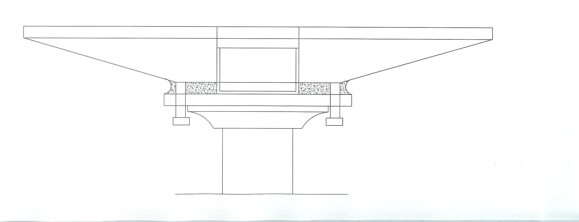
Following advice from Ottawa Optician Peter Caravolo who had done a few conic glass blanks, I glued the back of the mirror blank with very soft pitch to an 8 inch plate welded to a 2 inch diameter pipe flange. The flat on the back of the mirror blank being 7 inch diameter, this was a good fit to glue the blank to the flange. Before casting the pitch on the flange, I attached three small bolts at 120⁰ to the flange so that the small flat back end of the blank, where it is thickest, would rest. Without this, the glass would have gradually sunk in the pitch at an ever changing angle. I wanted the front surface to stay perpendicular to the axis of rotation of the turntables shaft, and concentric. The pipe flange would screw onto the spindle of the grinding machine (the spindle being a threaded steel pipe). A plastic tube was first fitted in the center of the flange to allow proper centering of the mirror and to provide latteral support in case the pitch flowed. I unfortunately don’t have a picture of this setup but here is a sketch showing the principle:
The glass blank stayed attached to the pipe flange for almost 18 months while I parabolized the mirror (yeah, I know, I’m slow). I was a little fearfull of what would happen when I would separate them. After all this time, the pitch had hardened and who knows how much stress might get relieved when I broke the bond. But Peter had provided good advice. There was no sign of stress being relieved after separation. Pitch is very forgiving.
Whenever I needed to test, I would grab the blank by it’s edge and simply unscrew it from the spindle. I would lift the 40 pound blank and attached flange and vertically attach it to the tester stand where a bolt would fix the flange to the test stand. When the mirror was in the test position, only the pitch was holding it thru that small bond in the back. I was always worried the pitch would break and the mirror come crashing onto the floor. I never left the mirror for more than one hour on the stand, knowing the pitch would eventually flow. The plastic tube in the center was a small security against a shearing break in the bond but nevertheless I remained worried. In the end the mirror always stayed perfectly glued and I never noticed any problems. This is how you hold a perforated conical mirror during parabolization.
Parabolizing was done with the mirror blank on the bottom, face up, and using sub-diameter tools. I had not made a mirror in close to 30 years (the last one being a 12.5 inch F/5.2) and had never worked with sub-diameter tools. I worked the rough parabola in with a 8 inch glass tool, Gugolz 55 pitch and cerium oxide. Here is a picture of the 8 inch tool at work:
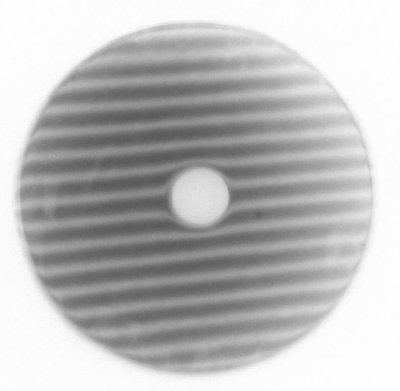
The machine would push the tool from side to side but it would also create a kind of “W” through the center thanks to the adjustable crankshaft on the left spindle which is just out of this picture. Although I roughed the parabola in this way, I quickly found that my machine was very limited in terms of controlling parabolizing strokes. So off came the overarm and I did most of the parabolizing strokes by hand, with four or five different diameter tools, from 2 to 8 inches in diameter. Parabolizing around the central perforation was always tricky and I ended up with a turned down edge around the hole, as can be seen in this birds eye view of an early version of the surface with a ronchi screen, as seen through a Ross null compensation lens (the outer edge TDE is also visible):
I wish to take a moment to thank Gordon Waite who came to my rescue at one point when I was stuck, unable to smooth out some zones without creating others. He provided some very helpfull advice. Thank you Gordon!
One lesson learned about sub-diameter tools: I should of made a 12 inch tool for smooting out the localized strokes with sub-diameter tools, which would tend to generate roughness (dog biscuit) on the surface. I liked the 8 inch tool because I could cold press it between the edge and the perforation. A larger tool would have required removing pitch from the center but I was lazy. I’m generally unhappy with the surface I created. It is rough at places (primary ripple), it has a TDE on the outer edge which I’ve had to mask (so far with ¼ inch mask but I will experiment this summer with larger masking) and it has some scratches. It performs OK, but it’s not great. I know I can do better and it will have to go back on the bench sometime in the next few years. I have a few mirrors to make in the mean time (including a 12.5 inch f/3) so I will hone my skills before starting over on the 20 inch.
In my youth I had always used a Foucault test but remembered from the 12.5 inch how difficult reading the shadows of a fast mirror was like. The 20 inch was even faster. So I machined my tester so it could perform the Caustic test, which I would use as a backup (see here for more details on the tester). Other tests that were tried were the Ronchi and the Ross null test. The Ross lens compensates longitudinal aberrations seen through the Foucault knife edge and Ronchi screens. The Caustic Test made me loose a couple of months because there was something wrong with my tester (see this CN thread for a discussion on those difficulties). I will get back to discussing my caustic tester, both in CN and in my website in a few months. I had initialy concluded that my 3 inch diameter Starret micrometer was no longer accurate. Turns out it’s fine. I traced the problem back to the hard rubber feet on which the tester rests. They are too soft! Working to 0.0001″ requires a lot of accuracy!
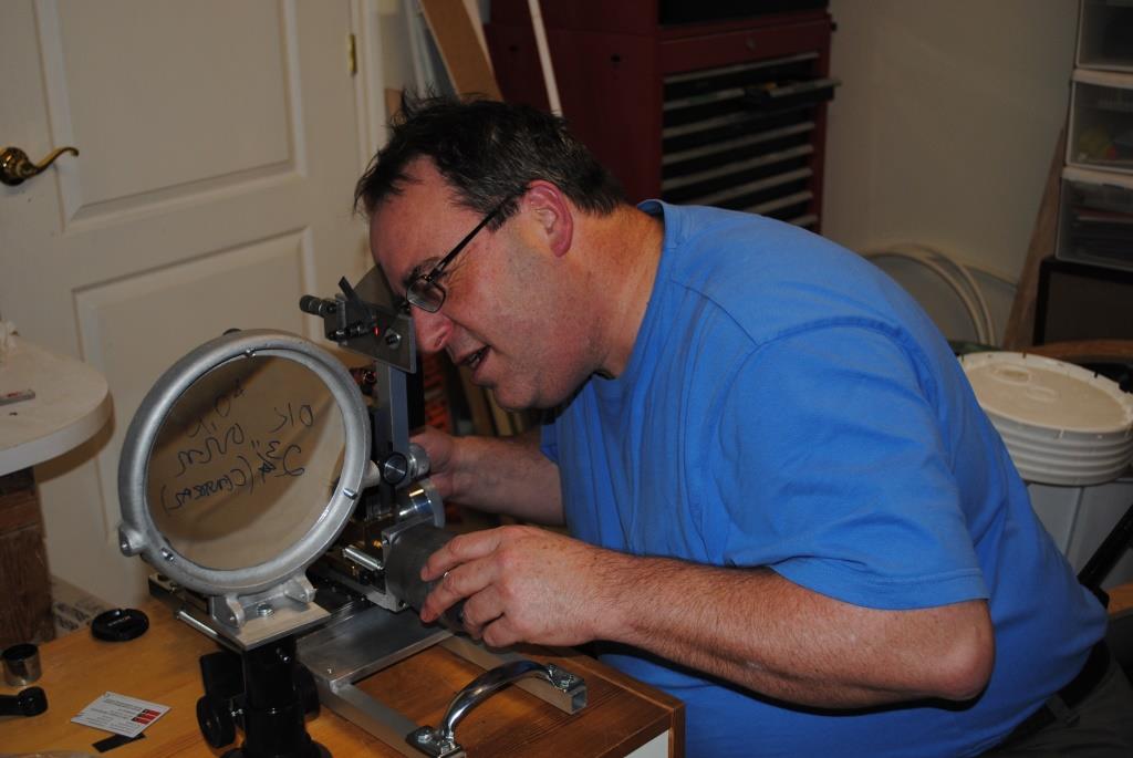
Here is a picture of me testing with a Ronchi grating. The large 6 inch Ross lens is set aside for now (I had not yet used it at this point, as you can see by the markings left by Peter Ceravolo when he had measured it) but it would be used later for testing.
After I decided I had enough working the mirror, I drove over to Canadian Optician and Telescope Maker Normand Fullum‘s house and left it with him to have it aluminized.