So, here I was with a very nice 2/3 plastic hemisphere of half the weight of my first hemisphere. I had done progress, but I was heading for a 100 pound OTA. Considering that in a ball scope the OTA IS the entire scope (well almost, you also need a short 5 pound tripod), 100 pounds for a 20 inch, non driven scope is pretty reasonable. For example a 20 inch f/4 classic Obsession Dobsonian telescope weighs about 125 pounds. After carefully examining my options it dawned on me that I didn’t need the whole 2/3 hemisphere. I found I could actually cut away part of the hemisphere with little consequence on ergonomy but with a major advantage in weight reduction. Cutting away part of the sphere would reduce the finished instrument’s weight but, as an added benefit, I could use the asymmetric hemisphere to balance out the eyepiece and finder weight instead of adding an offset counterweight at the bottom of the tube. All I had to do was always place the eyepiece cluster at the same location, relative to the hemisphere’s asymmetry. This was tested on my 6 inch ball scope prototype. I found I could point the telescope almost anywhere in the sky with few additional restrictions.
Here is a sketch that demonstrates the principle of the asymmetric hemisphere:
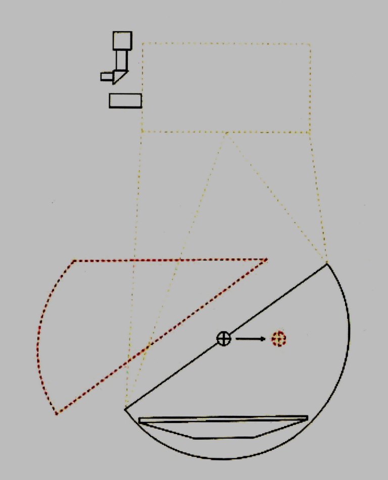
If you cut a big chunk of the hemisphere away as illustrated, the center of gravity (CG) of the hemisphere than shifts to the opposite side (to the right). All you need to do to re-balance the tube around the optical axis is to add eyepieces and finderscopes above the part of the tube that you cut away. This will bring back the CG towards the center. The rebalancing may not be sufficient, it depends on the thickness and density of the hemisphere material, the weight of the eyepiece holder, eyepieces and finder scope(s) but this will go a long way to re-introducing a balanced OTA. All without resorting to a counterweight (or using a smaller counterweight).
This approach brings advantages and, quite frankly, only very minor inconvenience to the system. Here are the two main advantages:
- Weight reduction. This is obvious because you cut away a significant portion of the hemisphere. But is is also a fact that you get rid of most, if not all of the offset counterweight you would have to install if you did not cut it away (folks making ball scopes often use lead shot sunk in resin when adding the offset counterweight).
- More rapid thermal balance of the primary mirror. Indeed, in a classic ball scope, the mirror is encapsulated inside a closed hemisphere from which heat does not naturally escape easily. Fans can be installed and holes drilled in the hemisphere but it is still very much a closed environment. By cutting away a big portion of the hemisphere any small breeze will carry the heat away from the mirror much more quickly, or even radiative exposure to the cold firmament.
I took a few weeks to think about this and muster the courage to cut up my hemispherical masterpiece. It seemed too good to be true, this weight reduction scheme. What if I was wrong (I have been known to make stupid mistakes)? I had spent probably 100 hours making this hemisphere and it was now perfect. Nevertheless, I took the bull by its horns and, trusting my instinct, went ahead with the operation. That is what prototyping is all about: trying, failing and trying again.
I first determined which portion to cut by measuring a 30 degree angle:
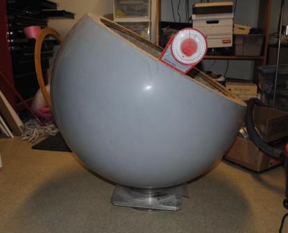
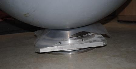
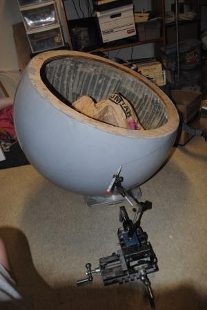
To measure where to cut, I mounted the hemisphere on a large 10 inch diameter Kaydon ball bearing race assembly from a currently unused 12 inch telescope mount I had lying around
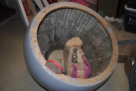
I added weight to the bottom so the hemisphere would stay at the correct angle during rotation, to mark the cutting line:
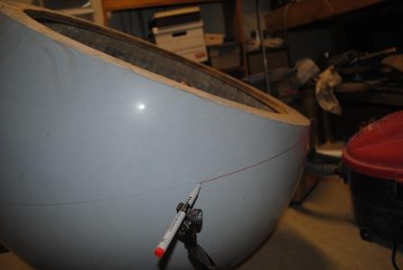
I approached a fine felt tip pen and rotated the hemisphere on the ball bearing, with the pen touching the hemisphere to mark the cutting line.
To my astonishment, I was pleasantly surprised to find the fine felt pen never lost contact with the hemisphere during its full rotation. This was a first indication of how accurately spherical and true the hemisphere was. Tracking stars with this surface would be a breeze:
I then used an electric hack saw and cut away the excess plastic from the hemisphere, using the line marked with the felt pen as a guide.
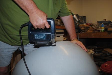
The operation was a success! I cut away 14 pounds of plastic and would eventually find out that the 6 pounds of eyepieces and finderscopes would almost perfectly balance out the missing piece of hemisphere, making a 6 pound side counterweight superflous. A weight reduction of 20 pounds in all, bringing the theoretical weight of the OTA down from 101 to 81 pounds.
Of course, after cutting the hemisphere up I had to make a new reinforcement ring because the original one had been cut away. The new ring, made up of two stacked and glued plywood discs, is the only wooden component in the entire telescope. I quickly found out, however, how important this ring was to the strength of the instrument.
The orignal ring, which had been cast in the hemisphere plastic, was very strong, even though it was only a single ¾ inch ring of plywood. It was perfectly glued all around and made the lip of the hemisphere very strong. The new ring, even though it was 1½ inch thick was bending under the stress of the UTA. I had used a couple of plywood discs from my shop and had been a bit sloppy in cutting up the lower of the two rings, which attached to the newly cut hemisphere lip. Also the cutting of the hemisphere, near where the old wood reinforcement ring was intialy glued during the hemisphere’s fabrication, was not of even thickness. The result, when I mounted the UTA with the trusses, was a low frequency, high amplitude vibration. The ring was not well fixed to the hemisphere’s top lip and there was a lot of local bending occuring under the bending stress of the UTA’s weight.
At first I wasn’t sure if the vibration was coming from the tracking platform (there were indeed some issues with this, as I explain here). The ring is where the truss tubes attach and there is a lot of stress at the fixation points. The hemisphere, by itself, has very little strength at its upper lip. This becomes especially apparent in this six pole truss design. So a second reinforcement ring was made with more care and a tighter fit inside the lip of the hemisphere. After encapsulating the ring in putty (to prevent humidity from eventually swelling the plywood) and sanding and painting, the ring was fixed to the hemisphere with 24, size 8 x ¾ inch long brass screws.
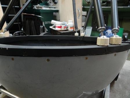
I had initialy put only 12 screws but could hear the scope cracking and complaining as it moved from horizon to zenith. Perhaps gluing it would be a good idea eventually but I wanted to keep the option of removing the ring if necessary.