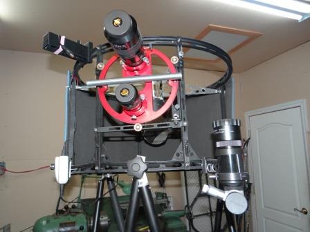
The upper tube assembly (UTA) is built around two aluminium bicycle rims. These rims have a 21½ inches inside diameter and 23 inches outside diameter. For a 20 inch f/3.9, this was an ideal size since no significant vignetting is introduced and the aluminium alloy used, as well as the profile shape, make for two strong, yet lightweight rings (1 pound each).
The two bicycle rims are 14 inches apart, separated by 5 aluminium U channels like those found in hardware stores. The U channels attach to the bottom rim through a small triangular gusset reinforcement plate to which the channels are tack welded.
As for the top ring, the U channels are attached only with a bolt. Like in the rest of the telescope all the nuts and bolts used to assemble the UTA are either stainless steel, brass or aluminium.
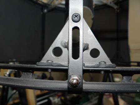
The UTA attaches to the three pair of truss tubes with large knobs that have 5/16 inch stainless steel bolts, as this picture shows:
I describe these unusual truss pole configurations in more detail here but you will notice the truss poles are not side by side, like in most truss telescopes, but instead one in front of the other. This was a prefered configuration because the attachement points are on the side of the bottom ring rather than on the bottom of the ring.
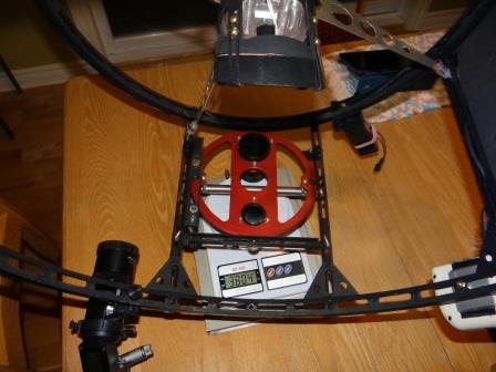
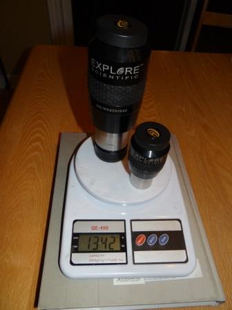
You will notice all the structural components of the UTA have slots milled out through them, including the bicycle rims. This feature was added a year after first light, when I was working on lightening up the telescope. The weight of the UTA has a huge influence on where the CG will end up being located. With a dobsonian, you can move the position of the altitude bearing to compensate a CG that is to high. But with a ball scope, the CG must be at the physical center of the hemisphere. To move it there you either do the lazy thing and add counterweights in the bottom or, find ways of lightning up the UTA. Here is a picture of the UTA on a kitchen scale without the eyepieces (weight is in grams):
And the two heaviest eyepieces I mount simultaneously:
The 2 inch diameter 20mm ES 100 AFOV eyepiece has a permanently mounted Baader MPCC coma corrector with spacer. The other eyepiece is a 1¼ inch diameter, 11mm ES 82 deg AFOV eyepiece. So, the UTA without eyepieces weighs 3.8 Kg (8.4 lbs) and the heaviest eyepieces I use simultaneously weigh 1.3 Kg (2.9 lbs), for a fully operational UTA weight of about 5.1 kgs (11.3 pounds). This weight includes all of the following:
- The two eyepieces
- Two helical crayford eyepiece holders (one 2 inch diameter, the other 1¼ inch);
- A Rigel reflex finder;
- A 7×50 RACI optical finder with illuminated crosshairs;
- A Kendrick four channel heater control;
- A light shroud;
- A 4 inch diagonal mirror
- A 4 inch heater pad behind the diagonal
- A diagonal holder and spider vanes
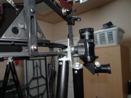
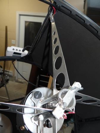
The only thing missing that would add a little bit of weight are heater coils for the optical finder and the 20mm eyepiece. Eventually I also expect to add a filter wheel. By the way, the diagonal heater pad is powered through the vanes which are electrically insulated from each other and from the UTA aluminum structure, using fiberglass bolts and rubber tubing at attachement points, as can be seen in this picture:
When it first became operational, the 20 inch needed about 15 pounds of counterweight behind the mirror to prevent the tube from falling to the ground. Today the scope can operate with no counterweights (although it is slightly better balanced when 2 pounds of counterweight are added behind the mirror). Slotting all the structural components and redesigning the diagonal holder reduced the weight by about 2¼ pounds. Switching from 1¼ inch Moonlite truss tubes to 1 inch ones and adding an onboard 12 V rechargeable battery attached to the hemisphere did the rest.
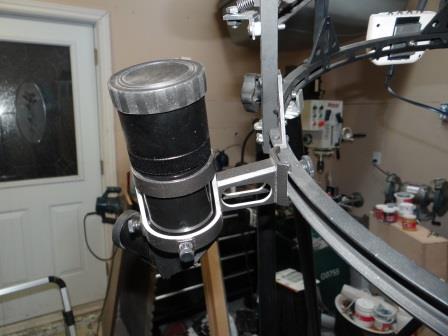
I even machined out the optical finder bracket by removing material I considered unnecessary, as can be seen in this picture:
So, in spite of it’s lightweight, is this UTA robust and rigid? It has issues and should be more robust. I’ve noticed a laser pointed throught the 1¼” eyepiece holder and projecting onto the center of the mirror will move by almost ½” as the telescope moves up and down in certain tube positions. I believe this is due to the top ring deforming. Indeed, I’ve noticed with using bicycle rims and spider vanes arranged like this: >o< is that if you squeeze the outer periphery of the upper ring with your hands, the diagonal mirror rotates slightly due to the rim deforming. I working on improving this problem.
