Making the Plastic Hemisphere
Now let me tackle the heart of the ball scope: the hemisphere. I had a lot of difficulty finding a 30 inch hemisphere in which to mount the optics. At some point I came to the conclusion that I would have to make it myself. By the way I use the generic word “hemisphere” to describe the “ball” (as in Ball Scope) but in fact that word can describe anything from a true hemisphere (half sphere) to a 2/3 sphere (like most ball scopes use). Semantics aside, from now on I will use the the term hemisphere to describe any portion of a sphere used for a ball scope.
During construction of my 20 inch ball scope, two hemispheres were made. I will start by describing the first experiment, the “blue” hemisphere. This first hemisphere fits the expression “the operation is a success but the patient died“. I learned a lot building the blue hemisphere and developped the tools that would make the second hemisphere, the “grey” hemisphere, a success. But in the end I couldn’t use the blue hemisphere because it was to heavy. I was aiming for an operational OTA of 75 pounds. Unfortunately the blue hemisphere weighed approximately 80 pounds empty. I put it aside (still have it) and found another manufacturing technique to lighten things up.
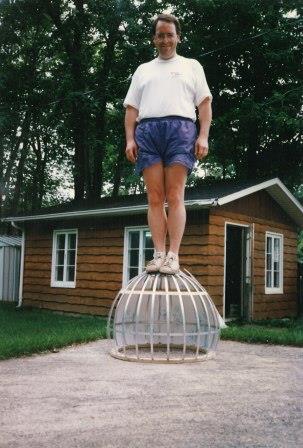
First, here is an early picture of the 20 inch mounted on the blue hemisphere:
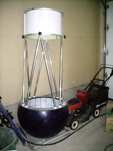
When this picture was taken the UTA was much heavier than it is today yet, the scope was still bottom heavy ! Here is a description of the construction technique I used to make that first hemisphere, which can be seen in the attached photographs:
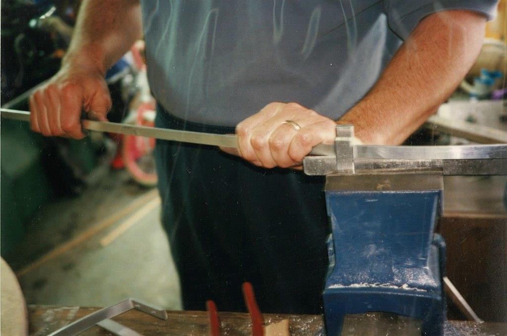
- I purchased and cut a bunch of ¾ inch wide 1/8 inch thick aluminum flat bars that I would bend to form a hemispherical lattice.
- I had a friend cut on a CNC lathe a 12 inch diameter x ¾ inch thick disc of aluminium that was flat on one side and curved to a 15 inch radius on the other.
- I drilled and tapped a ¾ inch hole in the center of the aluminium disc and three holes for the mirror collimation bolts (see here for a description of the mirror support).
- I cut two ¾ inch plywood rings that would reinforce the lattice and form the attachement points for the truss.
- I assembled the lattice using the curved flat bars
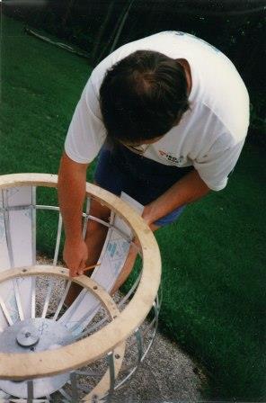
- The 24 flat bars were joined at the bottom on the curved aluminum disc and thick cardboard was cut to shape and glued to each of the flat bars, to form a hemisphere ready to be covered with a stronger material
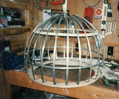
- The skeleton hemisphere was fairly light at this point but very sturdy, as the following picture shows:
- A large disc was attached to the top ring of the hemisphere and bolted down on the central shaft of my grinding machine.
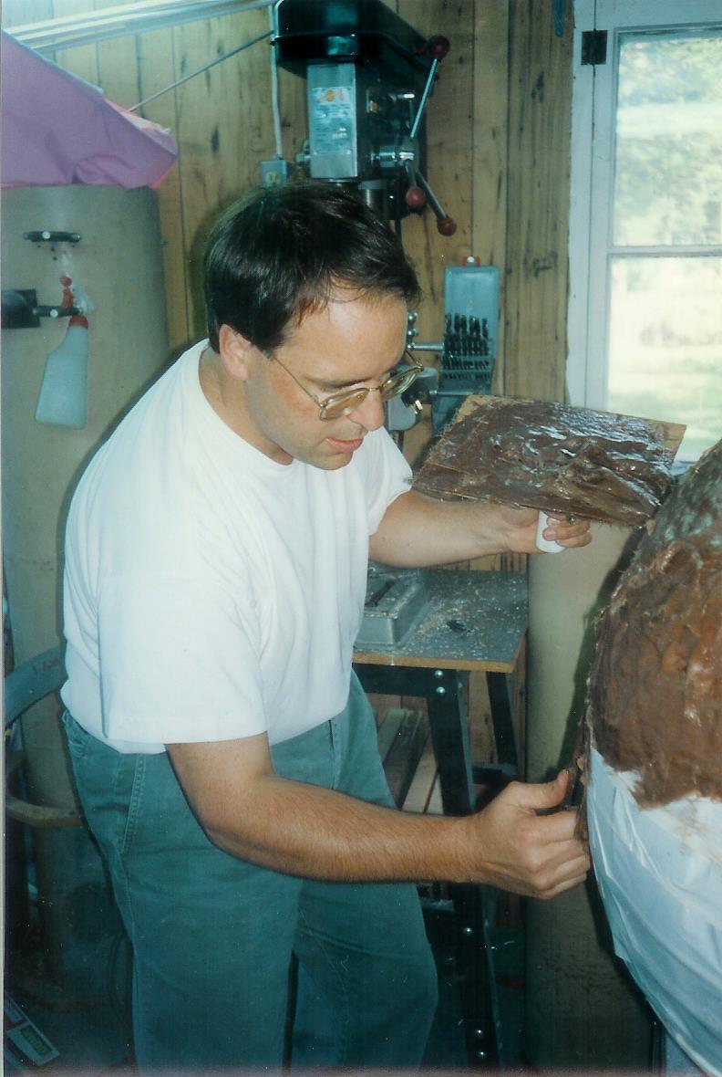
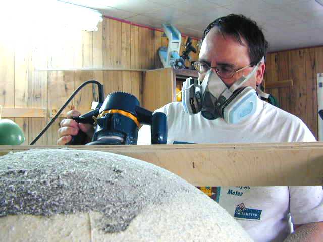
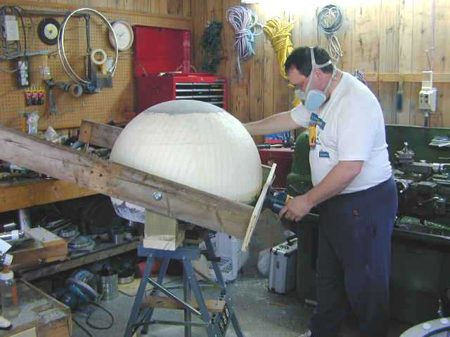
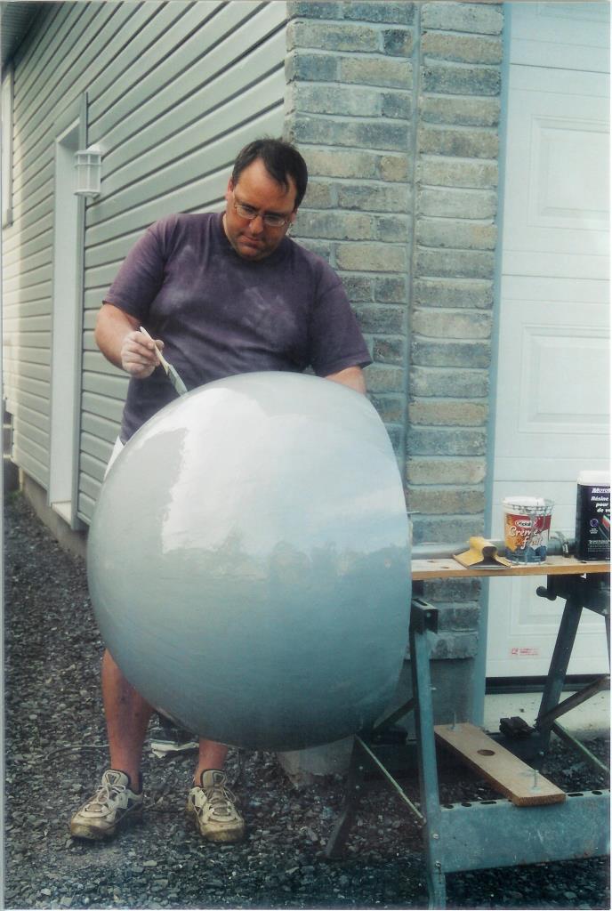
- Autobody filling putty was applied to the surface of the cardboard hemisphere. This putty is sold with no glass fibers in it, short glass fibers and long glass fibers. After experimentation I found the short glass fibers worked well and would probably provided some extra strength over no glass fibers. Here is a picture of a younger (and thinner !) me applying the stuff:
- A pivoting scalfolding was made using various wood pieces and mounted in such a was that the pivot was positioned in line with the center of the hemisphere.
- A router with a ¾ inch diameter end mill was mounted on top of the pivoting scalfolding. After applying the putty and letting it harden, I would pivot the spinning router up and down while the hemisphere would slowly turn below. Cuts were taken on high spots and craters were filled before cutting again.
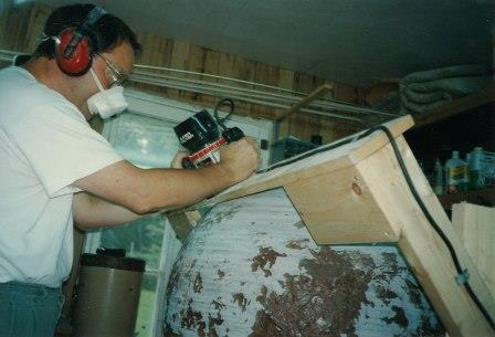
- When the hemisphere was reasonably free of high spots and craters, the cutting marks left by the router bit were sanded smooth. To do this I mounted a long 1½ inch diameter pipe to the hemisphere and chucked the whole thing in my Colchester lathe, as shown in this photograph:
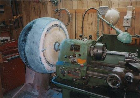
With the hemisphere slowly rotating in the lathe (about 30 RPM), I sanded with a small orbital hand sander. IMPORTANT SAFETY NOTICE: USE PROPER RESPIRATORY PROTECTION WHEN DOING THIS TO PROTECT FROM AIRBORNE PLASTIC AND GLASS FIBER DUST.
I don’t have pictures of the next operation but it consisted of applying generous amounts of fiberglass resin impregnated with a blue dye. After application the hemisphere was rotated by hand while the resin gelled (to prevent drips) and was left to dry. A little bit of sanding was done on the surface and another coat of blue dyed resin applied again. This was repeated for about 8 coats. After the last coat was applied, the hemisphere was sanded with the same orbital hand sander with finer and finer sandpaper (500 grit).
A few lessons were learned from this first hemisphere:
- The lattice was not perfectly circular everywhere so at places there was up to ¾ inch thick putty and at other places, less than 1/8 inch.
- Making the lattice and preparing the cardboard were time consuming jobs in themselves.
- Due to the difference in thickness, putty had to be built up until a reasonable minimum thickness (1/8 inch) had been built up everywhere. This made the hemisphere very heavy (80 pounds). Also, more than 5 gallons of putty were used, a lot of it going on the floor (expensive).
- The final sanding with the orbital sander resulted in a series of flats all over the surface instead of a uniform surface (kind of like ripple on a glass surface).
- The pivoting scalfoding, holding the router in such a way as to generate the curved hemisphere in hardned putty worked very well.
With these lessons in mind, I set out to find a better way to make a lighter and smoother surfaced hemisphere. A few years would pass before I would come up with a better method. Here, now, is a description of that improved technique.
A Lighter Plastic Hemisphere
Since the first hemisphere was much too heavy (80 pounds), I decided to make a second one using an improved, and simplified manufacturing method. The following describes this new method and can be reproduced by anyone with simple electric hand tools over a period of a few weekends.
Like my first, blue hemisphere, the second hemisphere is made of epoxy putty, impregnated with short glass strands. Here is a description of the manufacturing technique I used for my 30 inch ball scope:
- Instead of using my grinding machine as an axis of rotation (which was being rebuilt), I decided to use, instead, a Black and Decker Workmate workbench table. A large 24 inch diameter disc of ¾ inch thick plywood was cut and attached to a 1½ inch diameter pipe after drilling a corresponding 1½ inch hole, in the center, with a hole saw.
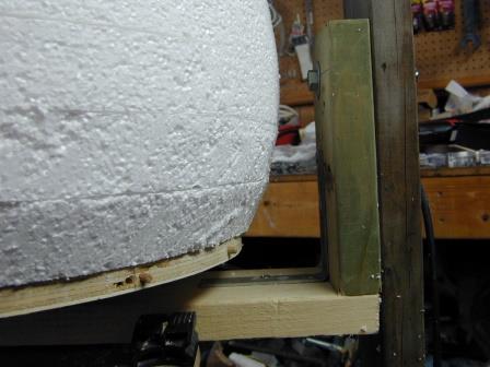
- The pipe was attached vertically to the workbench. A 2×4 is in the middle of the workbench and the pipe goes through the center. There is also a 2×4, attached to the workbench near the ground that the pipe also goes through. This setup creates a stable vertical axis of rotation.
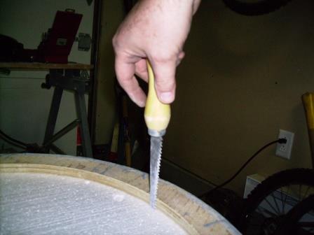
- A dozen discs of 2 inch thick construction grade Styrofoam of varying diameters were cut, to make up a rough 30-inch sphere. A quick sketch was first drawn up to determine an approximate angle of cut for the edge of each 2 inch thick section, using a large tooth hand saw (a bread knife with large teeth would probably work just as well).
- The 2 inch thick styrofoam discs were stacked on top of each other, through the 1½ inch pipe (1½ inch holes were drilled with a hole saw in the center of each styrofoam disc). This created a very rough, truncated hemisphere with a flat top.
Here is a sketch showing the overall setup before “milling” begins:
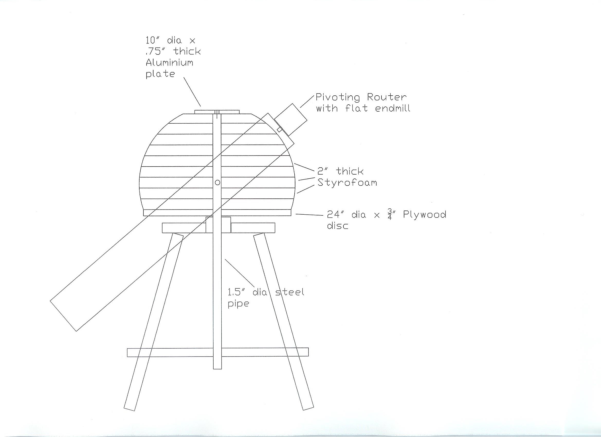
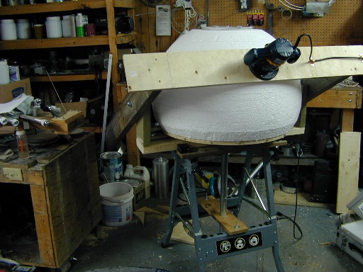
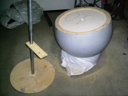
And a picture of the overall setup. As you can see, anyone can assemble such a jig to make any hemisphere, in any diameter:
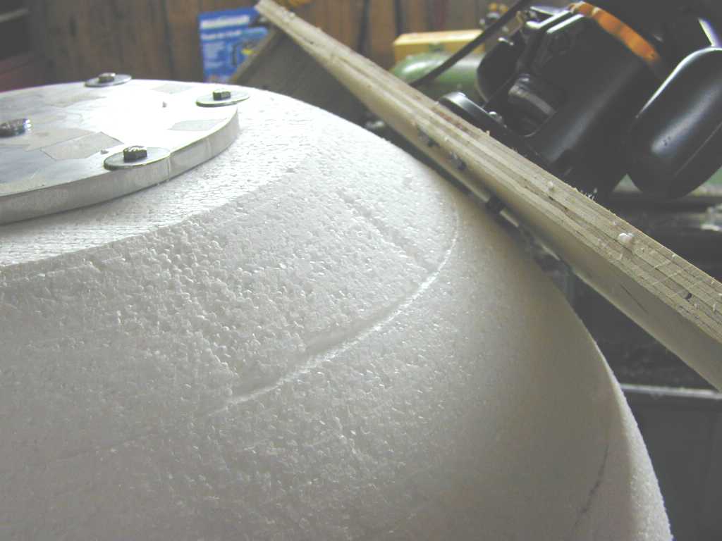
- The ¾ inch thick aluminum plate that serves as the anchor base for the mirror support and collimation system (see mirror support description here for details) was separated from it’s assembly and placed upside down on top of the last Styrofoam disc. Like for the first hemisphere, this disc defines the bottom of the hemisphere. However, instead of having a 15 inch machined radius, it is just a flat plate, which is a lot easier to purchase. The 1½ inch pipe that goes through all the Styrofoam discs ends with a ¾ inch diameter threaded rod, which screws into the center of the ¾ inch thick aluminum disc (the same threaded hole where the mirror collimation tightening bolt screws in).
- The picture of the aluminum disc shows six large washers fixed to it that stick out from the bottom. These washers contribute to anchor the large aluminum disc into the putty so that it cannot slip out during use. I didn’t want to just rely on the adhesion of the putty on the aluminium surface. Also, all exposed holes in the back of the aluminum plate are covered with masking tape so that no putty can get in. These holes, both threaded and smooth, support the primary mirror’s collimation mechanism.
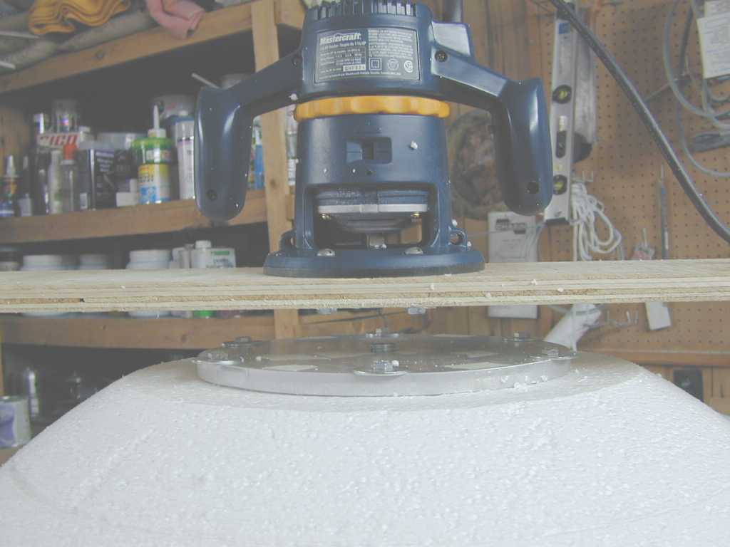
- A router was then mounted on a pivoting arm that surrounded the work area, just like I did with the first hemisphere. The pivot axis is aligned to be perpendicular to the vertical axis of rotation of the rotatable pipe and Styrofoam discs and the interrupted pivot axis is also going through what will become the center of the hemisphere.
- The router is first used to smooth out excess material on the Styrofoam until a more or less perfect hemisphere is produced. The router is controlled with one hand, moving it rotationally up and down while the tool spins. The other hand rotates the slab of Styrofoam discs until the router bit has completely cut away all excess Styrofoam, creating an almost perfect hemisphere.
- The router bit is then pulled back, away from the Styrofoam surface, enough to create the required wall thickness of the shell. Through experimentation I determined that a 3/16 inch thick wall thickness should be sufficient for this size of hemisphere and the expected weight of the instrument. In use, this wall thickness has proven sufficient and a good compromise between rigidity and weight.
- With everything now in place, application of the putty could begin. This is done with proper eye, ear and respiratory protection. Before applying putty, I first covered the Styrofoam with masking tape to help with Styrofoam removal at the end of fabrication. I also covered it because the epoxy resin in the putty would have “eaten” the foam during application.
- I started applying putty to the top of the sphere where the large aluminum plate was located. I was careful to first impregnate putty all around the six anchor washers on the ¾ inch thick aluminium base plate. I then added putty to cover the aluminum plate. I let the putty harden and took cuts with the router until I had a hard plastic dome.

- I then applied putty to the edge of the hemisphere. Here, also, I had taken the time to insert wooden anchor dowels in the side of the plywood disc to ensure the disc, which would become the hemispheres’ reinforcement ring once the center was cut away, would be well attached to the shell.
- Finally I applied putty everywhere else, to a thickness of 3/16 inch, thickness always governed by the initial adjustment of the router bit. The putty was applied like icing on a cake, allowed to harden and cuts taken. Craters were filled and excess, cut away. In retrospect it is better to do this outside. The putty smells strongly, even after it has hardened and it’s a mess to clean up afterwards.
Sanding and Finishing of the Second Hemisphere
When putty had been applied everywhere and the router had made its final cut, I took the router and it’s pivoting support off and started sanding with a small, hand held electric sander. I first used rough sanding paper to remove the cut marks left by the router bit and progressed on to finer sandpaper grits.
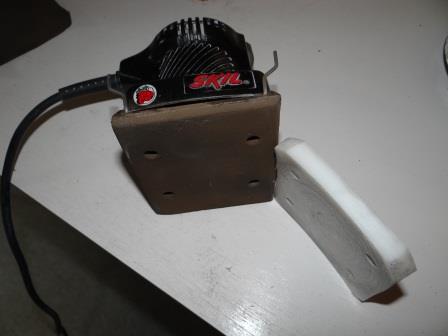
You will remember from the first hemisphere that sanding with a standard orbital finishing hand sander, had resulted in small flats all over the hemisphere instead of a smooth curve. So, for fine sanding I made a new, backing plate with a 15 inch radius. I used some kind of nylon or acetal plate I had lying around in the shop but this could also be made with plywood. I used a radius bar in the lathe to cut the curve. This could be done in a wood lathe as well. I then attached this new backing plate to the sander, instead of the flat one it normally comes with. This way the sandpaper was conforming more to the radius of the sphere, creating a much smoother overall surface. Here is a picture of the electric sander I used and the special sanding plate that I can interchange by just unscrewing the four bolts in the center:
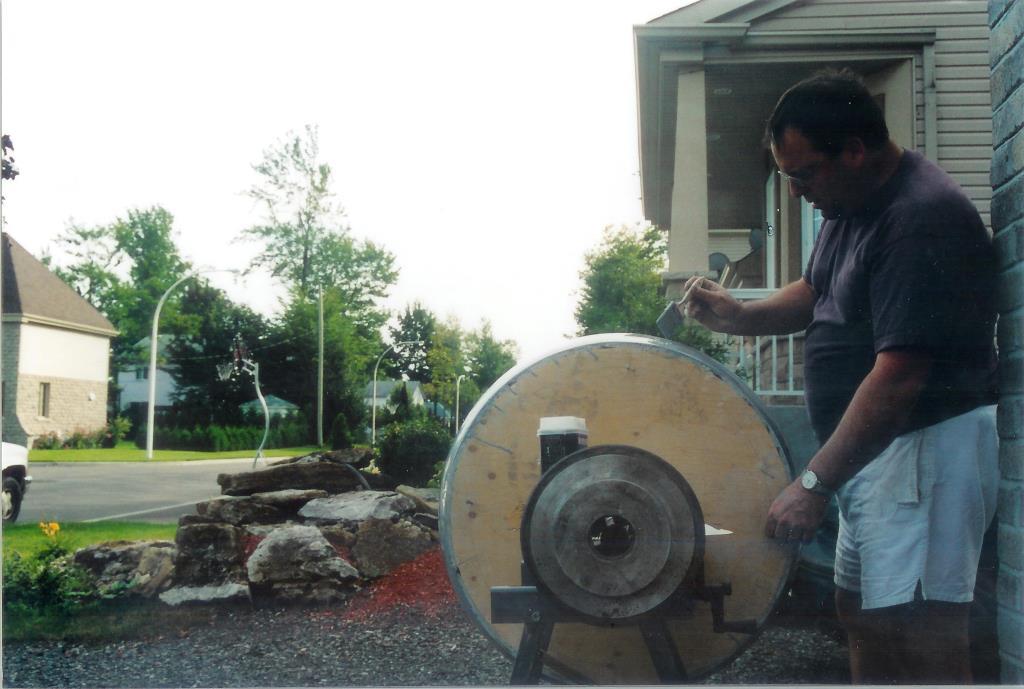
When fine sanding was complete I moved the sphere’s axis of rotation from a vertical to a horizontal position on the work bench. I placed a heavy weight at one end of the pipe (a heavy 4 jaw chuck I had lying around) to balance the weight of the hemisphere. I could still rotate the sphere but in a horizontal plane. This way I could apply generous amounts of liquid epoxy resin impregnated with a grey dye (any color would do but for this new hemisphere I just happened to have that color on hand). After the epoxy was applied I would spin the hemisphere by hand until the epoxy started to gel (about 30 minutes), just like I had done on the lathe for the blue hemisphere. This spinning prevented the resin from flowing under gravity, dripping and creating hardened drops. I temporarily nailed four nails into the top plywood disc so I could have something to grab onto to spin the hemisphere. After a few hours the epoxy had fully polymerized: I sanded a few minutes to rough up the surface for the next coat and I would repeat the procedure. I applied about 8 coats this way which created a smooth, thick epoxy surface. I did not need to paint and if the hemisphere is ever scratched I only need to sand again for repair.
I finished with finer and finer sandpaper (up to 500 grade) using the small orbital electric finishing sander with its curved plate support. This fine sanding, by the way, was the most tedious and boring part of the project. I estimate I sanded for at least 20 hours to get the finish I wanted. I found the sandpaper I was using kept cloging up with resin dust and the paper had to be frequently changed. There must be better sandpapers than the ones I was using but I have limited experience working with fiberglass. In the end the sphere was very shiny and very smooth.
Here are a few photos showing the application of the coloured resin: 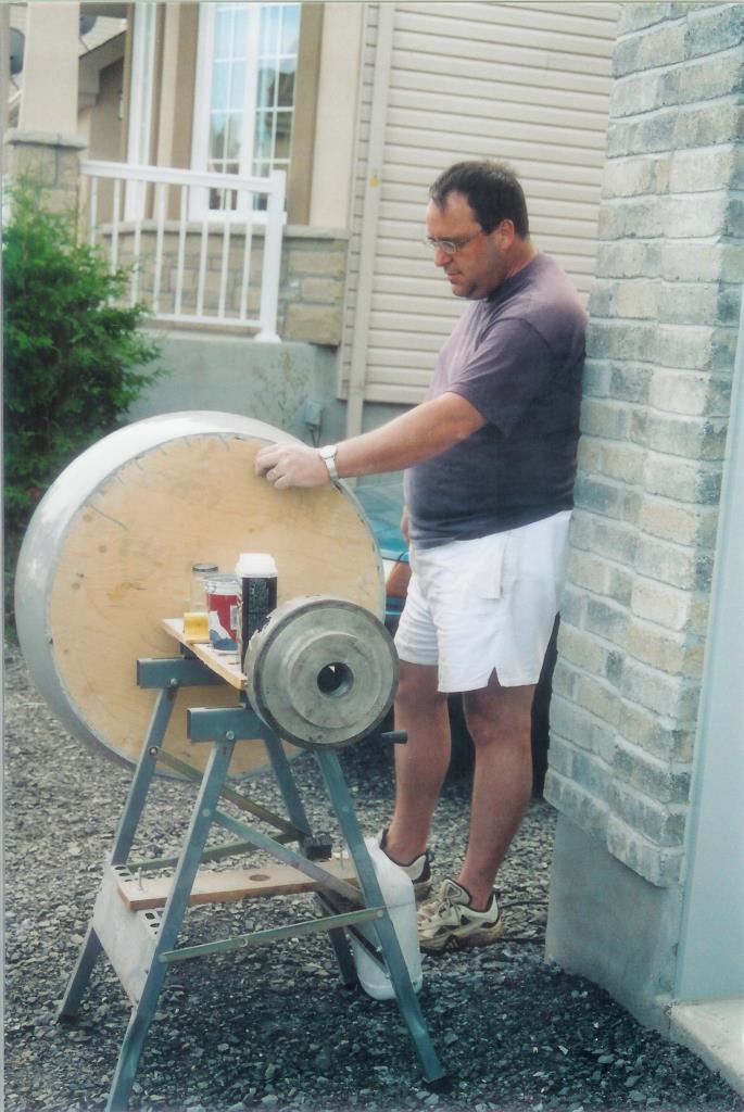
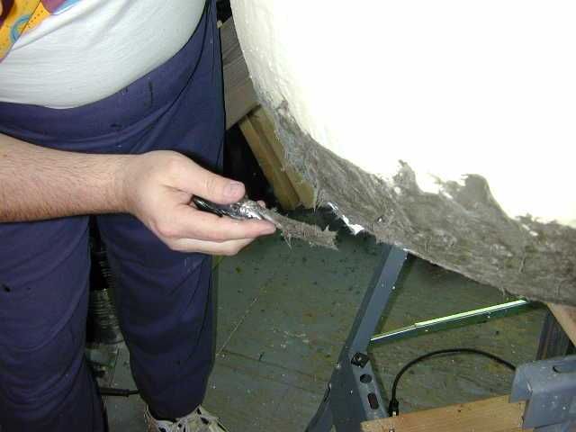
When I was satisfied with the surface finish of the dye impregnated epoxy resin, I removed the pipe and cut away all but a 2 inch wide ring from the central plywood disk. I did this with a hacksaw after drawing a cutting circle.
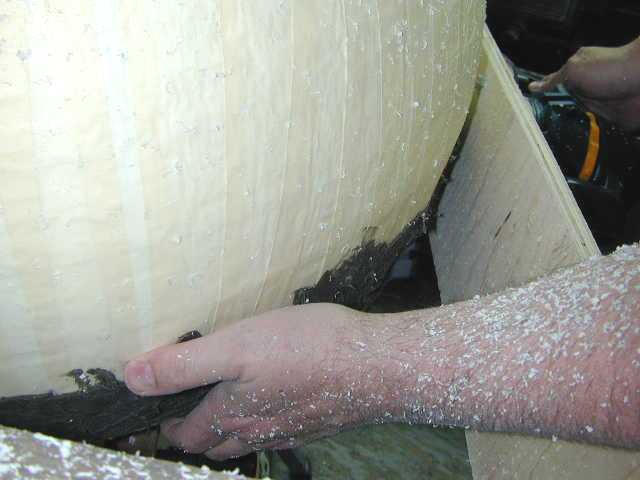
With the plywood disk now removed the Styrofoam core was exposed. I proceeded to extract the Styrofoam by cutting the slabs up in large, broken chunks and removing them (another messy operation). I was then left with a hollow, 3/16 inch thick hemisphere that now weighed only 40 pounds when empty.
Forty pounds was much better than eighty pounds but made it impossible for me to attain the 75 pound OTA weight I was aiming for. Indeed a rough calculation indicated the following:
- 40 pounds for the hemisphere
- 32 pounds for the blank
- 5 pounds for the mirror cell (excluding the weight of the 10 inch x ¾ inch thick plate that was now part of the hemisphere)
- 6 pounds for the trusses
- 12 pounds for the UTA
- 6 pounds of side counterweight to balance the tube around the optical axis
For a total of 101 pounds. I was getting closer to my 75 pound weight goal but would be unaible to reach it with this configuration. I had to find a way of reducing the overall weight by 25 pounds. But how? Find out here.