Primary Mirror Support
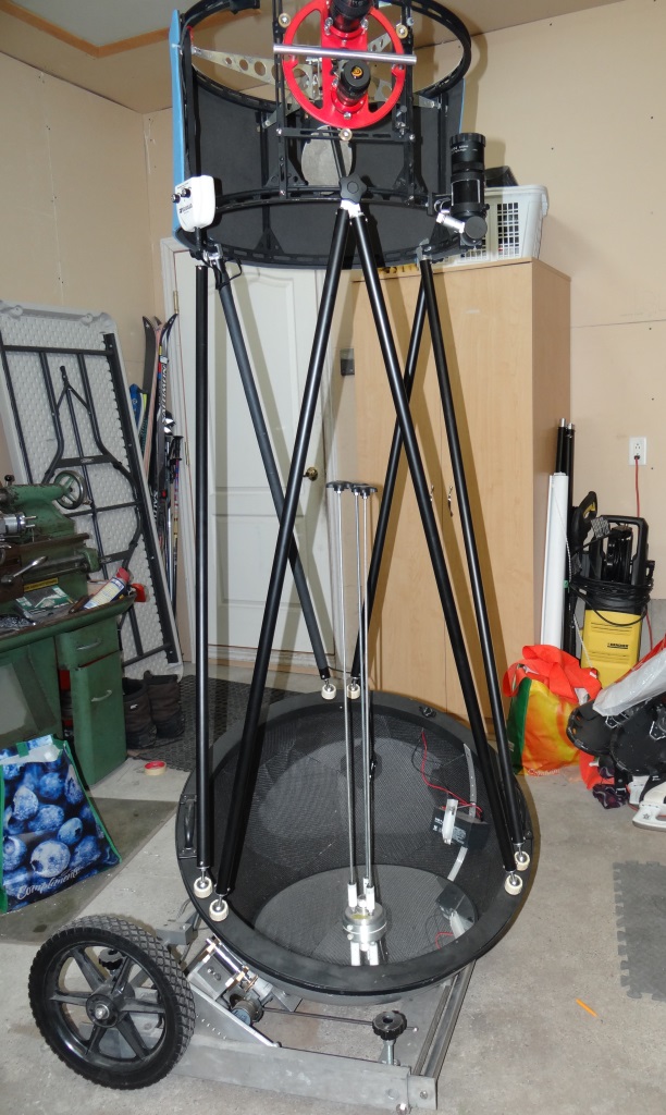
The primary mirror support is a mix of simple and clever. Due to the tracking equatorial platform design that the telescope is mounted on, the hemisphere surface acts not only as the tube bottom but is also an integral part of the pointing and tracking surface. It is preferable that the mounting surface not be compromised with large orifices that would both weaken the skin of the hemisphere and momentarily throw tracking off when a hole would be going over one of the rollers on the platform, below. Mounting the mirror, including provision for collimation, had to take this restriction into account.
In a dobsonian, the mirror cell must prevent sag of the mirror surface when the instrument is looking near the zenith (worst case) and accomplishes this by distributing the weight of the glass on floatation pads in such a way that the image is not seriously degraded. This subject is frequently discussed on ATM forums and the mirror cell parameters can be calculated using a very practical Finite Element Analysis (FEA) shortcut developped by Canadian ATM David Lewis, called PLOP. The other mirror support necessary in a Dobsonian is the edge support which prevents the glass from sliding off the floatation pads located under the mirror. Depending on the glass thickness, diameter and focal ratio, the edge support of the glass can be anywhere from insensitive to extremely sensitive to image deterioration when the tube leaves the confortable position of verticality and adventures itself to a more inclined position. The sensitivity of the edge support can also be estimated using another FEA shortcut developped by Belgian ATM Robert Houdart and available on his Cruxis web site.
I’m telling you all this to emphasize the fact that a ball scope has many more degrees of freedom of movement than a Dobsoninan. A mirror that works in a PLOP and Cruxis developped Dobsonian will not necessarily work in a ball scope, or even an equatorial mounting for that matter. As a matter of fact, if the mirror is thin/large/fast enough, it may even have difficulty handling a Poncet type equatorial platform without introducing strong astimatism. So when designing for a ball scope one needs to take the limits of the glass into account and use a sufficiently thick piece of glass whose entire weight can be supported on a single edge support without seriously deforming. It’s a paradigm shift for ATMs used to dobsonians.
To go bigger in diameter without a serious increase in weight or cool down time, one must use alternate glass shapes. Some cellular engineered blanks will be able to handle larger diameters in equatorial mounts or ball scopes (like Dream Cellular or Hercules) but they are very expensive. The solution I chose (actually I think it chose me !) was the conical mirror blank. The mirror support for this type of glass shape is extremely simple. There is no need for floatation cells and edge supports. Held only by the thick central part of the glass, the mirror deforms in an acceptable maner (see here for a discussion on conical mirror deformations). For those interested, conical blanks are available from Newport glass in California and conical mirrors from R.F Royce in Conneticut. Some professional mirror makers like Mike Lockwood also have experience working this type of glass.
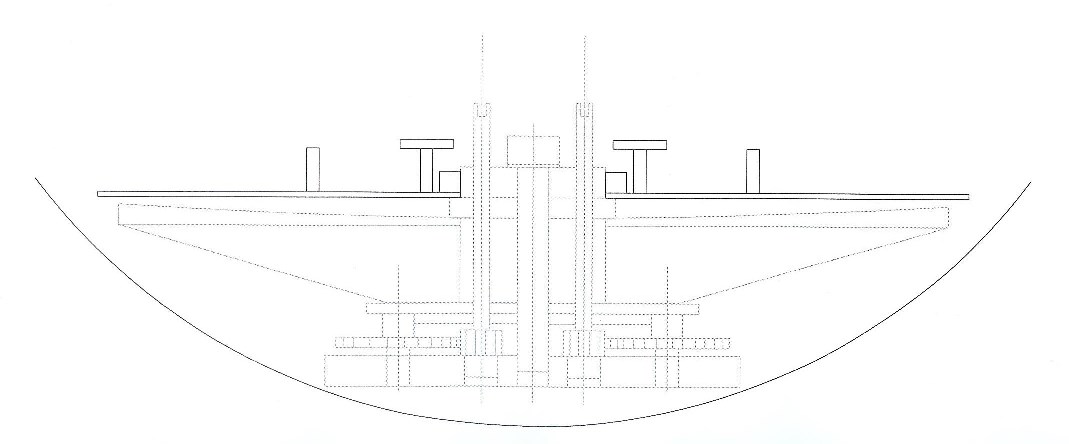
Here is a sketch showing how the 20 inch diamtere conical mirror fits inside the 30 inch diameter hemisphere:
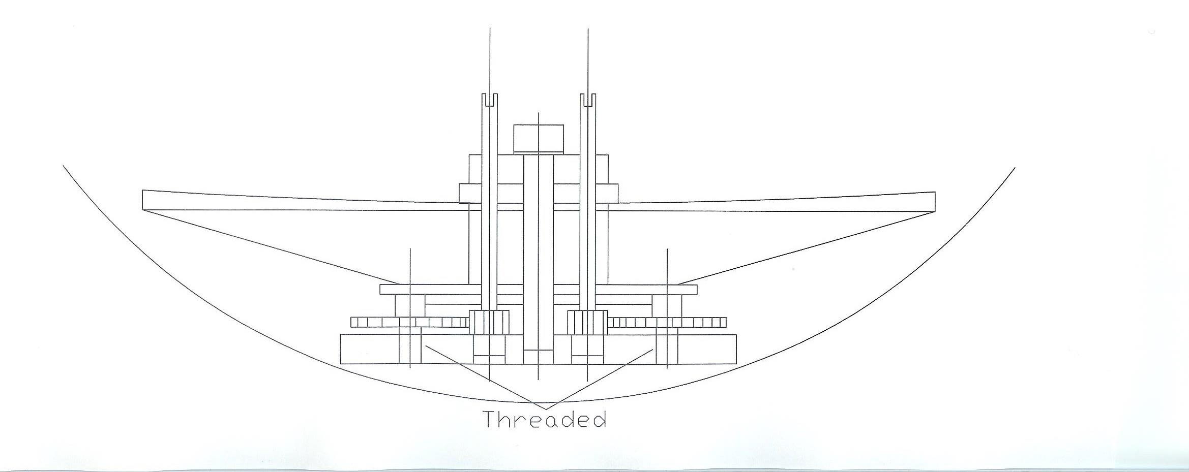
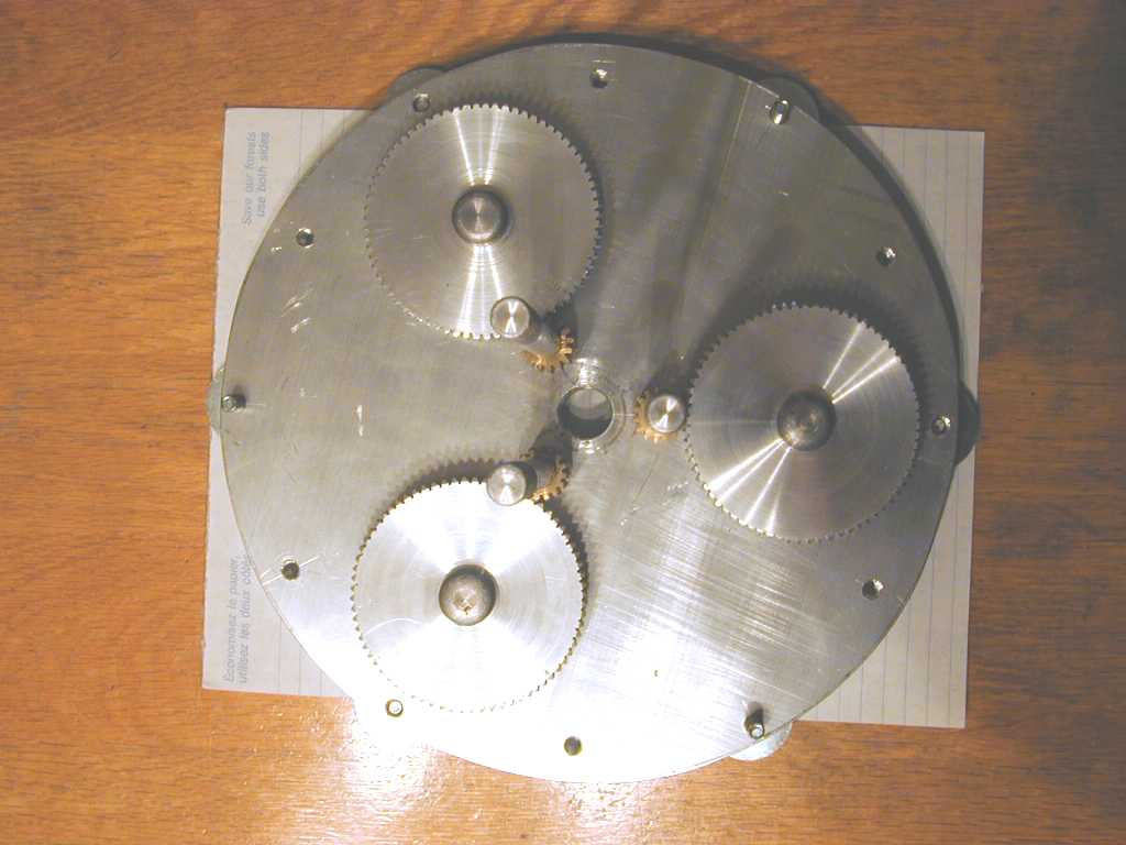
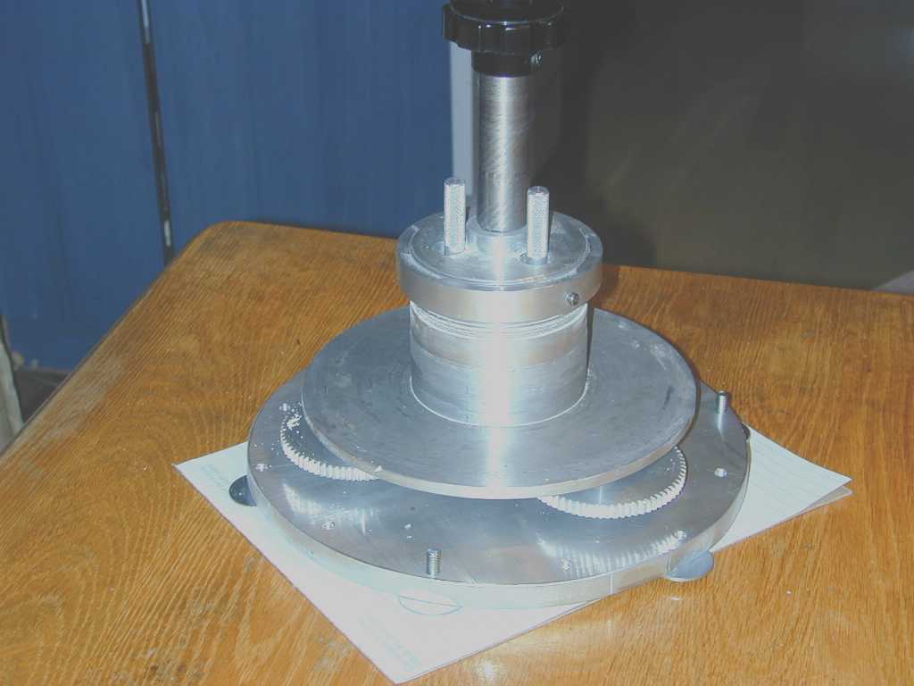
EXPLANATION OF THE MECHANISM: The 7-inch diameter flat central portion on the back of the mirror rests on a ½ inch thick, 8-inch diameter aluminum plate, attached with four hex bolts to a 3.5 inch diameter solid aluminum core. In turn, the 8-inch plate rests on three, ½ inch bolt heads that thread into a ¾ inch thick and 10-inch diameter aluminum back plate, embedded in the epoxy that makes up the plastic hemisphere. The ½ inch bolts mentioned above constitute the hub of 3 inch diameter spur gears. These three gears mesh with three brass splines, which are connected to long, thin shafts that stick out above the solid aluminum core, through three long holes. The bottom of the brass splines were machined round and run in bronze bushings fixed in the thick aluminum plate. The top end of the shafts are knurled to provide a good grip while collimating and have central slots (slots had not been cut when these pictures were taken). These slots serve to attach 3 foot long extension rods that allow me to collimate through a high power eyepiece when the telescope is pointing straight up. The shafts run through holes in the 3.5 inch central core much larger than the shaft diameters (to allow for inclination of the mirror support, without interference from the straight shafts). The shafts are loose but the bottom of the hole in the core is a little smaller than the spline diameter so the assembly remains captive. Each of the three spline/spur gear arrangements is installed at 120 degree angles from each other. A 5 inch long ¾ inch diameter stainless steel hex cap bolt screws into the center of the ¾ inch thick aluminum plate. When collimation is completed, this bolt tightens the whole mirror support assembly together, preventing any movement. Of course, when this pressure is applied the mirror remains unstressed, resting loosely on this support.
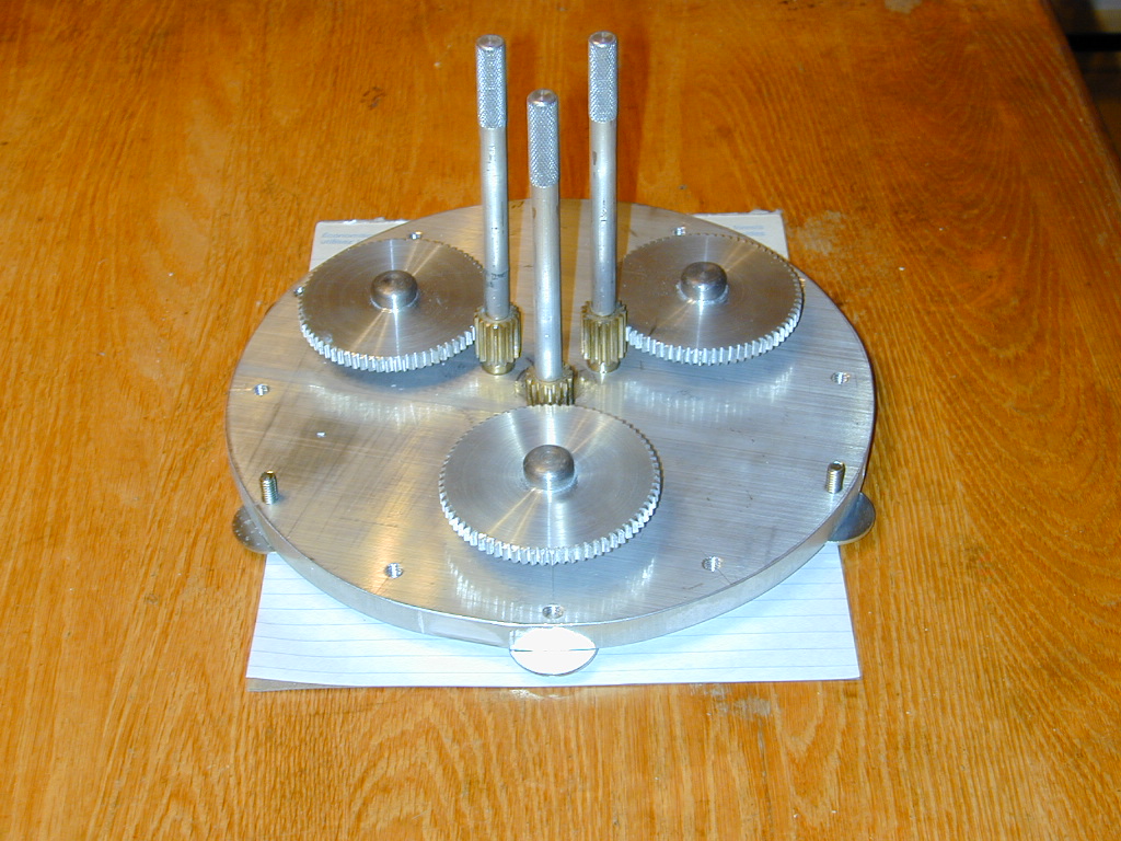
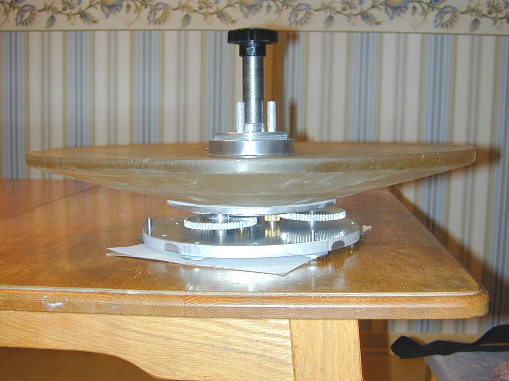
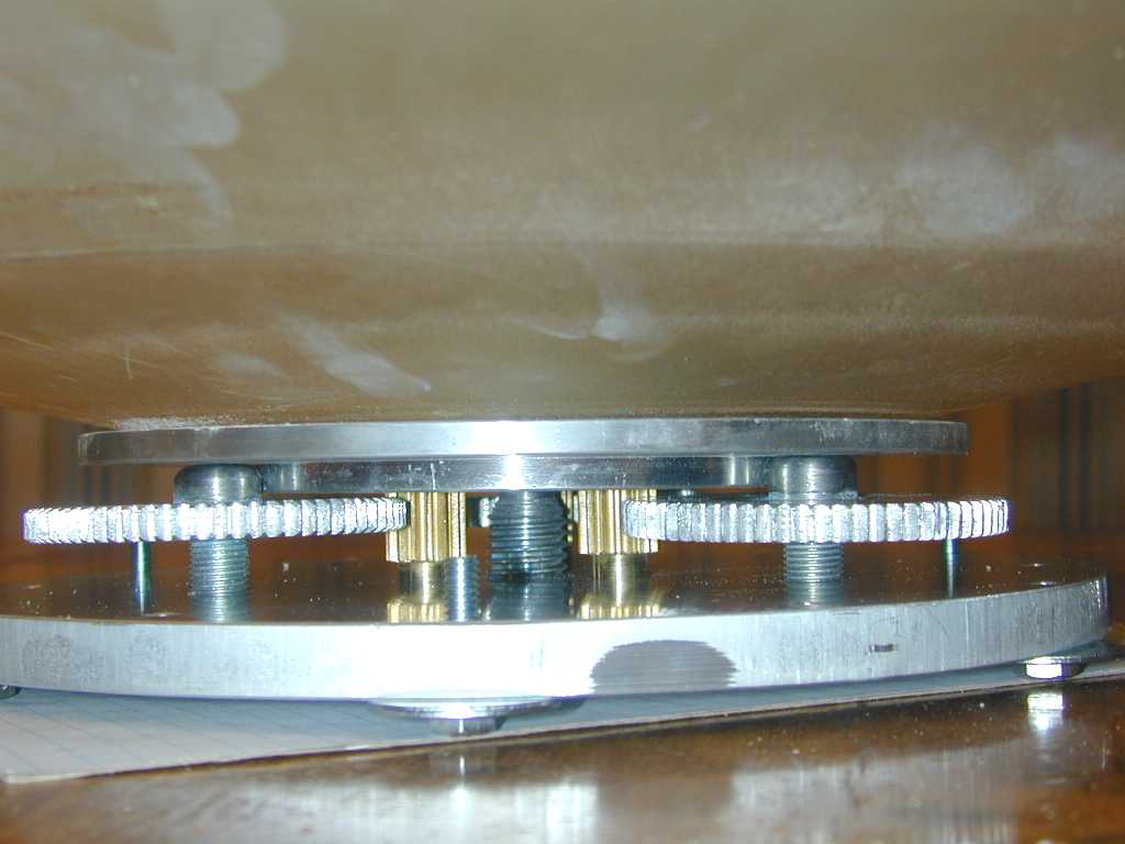
Here are a few self-explanatory pictures showing the mirror cell before it was imbeded in the hemisphere. Note that the central ¾ inch bolt that tightens everything down was a long threaded rod attached to a large knob when these pictures were taken. They were since replaced with a shorter stainless steel machine bolt.
One inconvenience with a perforated mirror is that collimation cannot be done with the usual Cheshire or Laser collimation tools since the center of the mirror is non-existent. Instead, a simple peep hole is centered in the eyepiece holder and the adjustment screws turned until the 4 inch diagonal mirror image seen in the mirror is centered with the 4 inch diameter mirror retaining ring. This alone will get collimation in the ball park but, collimation must be followed up with examination of a bright star near the zenith for further fine tuning of the primary mirror alignment. I made three, 36 inch long extension rods that attach to the small, protruding collimation knobs (see below). This makes accurate collimation using a star much easier and more accurate, because I can collimate the primary while simultaneously examining the out of focus star image. This collimation is made all the much easier because the telescope is driven.
Additional discussion on mirror support
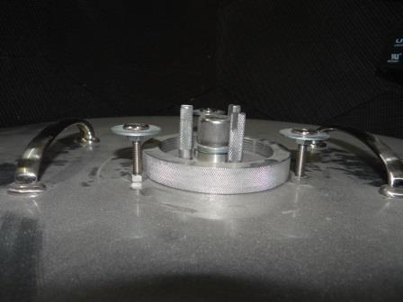
Here are a few more thoughts the mirror support. First a few pictures showing the collimation knobs today, with aluminized mirror in place.
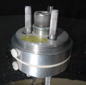
This first picture shows the three knurled and slotted adjustment knobs sticking out over the central post, surrounding the ¾ inch diameter machine bolt that thightens everything together. You will notice there is a lock washer between the ¾ inch bolt and the 3½ inch diameter solid post so as to prevent mirror support from unscrewing under vibration. One last detail: that yellow Canada sticker with a serial number, visible on top, was placed there by Canadian customs officers to register the telescope and certify it originaly came from within Canada when I first brought the 20 inch to the United States for the 2013 Stellafane convention.
In the second picture, two of the three extension rods are in place for remote collimation. The extension rods are simple, ¼ inch diameter threaded rods. On the mirror end I’ve slipped a teflon tube over the threaded rod, accross which a spring pin was pushed in. This pin inserts into the slot of the short adjustment knobs sticking out over the center support. I used teflon instead of aluminum as a safety measure: Should I unknowingly pull one of the rods out and it fell on the mirror, there would be less dammage and scratches with teflon (could have been nylon or some other plastic but I happened to have teflon tubes in my scrap box). On the upper end I currently have three large plastic knobs but they are unnecessarily big. I will soon replace them with ½ inch diameter knurled aluminum knobs, making storage easier and keeping the extension rods more within the shadow of the diagonal mirror during collimation:
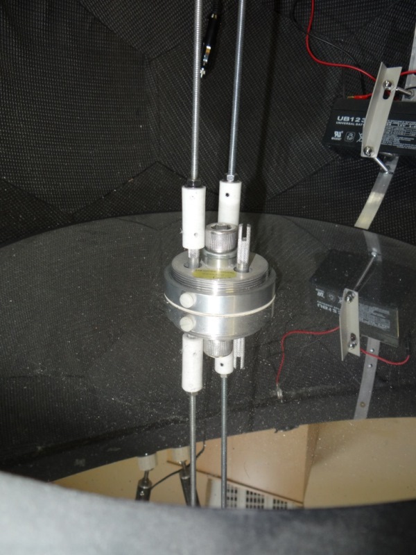
The last picture shows an overall view of the 3 foot long extension rods extending about halfway up the tube. I can collimate flat footed on the ground when the telescope is 10 degrees away from zenith. However I prefer to stand on a small stool and look for a star closer to zenith so that there is minimum disturbance of the collimated setting when I thigten down the central bolt. By the way the eyepiece height above ground is a little under 72 inches and my eye is at about 67 inches.
If I were re-designing this telescope today, I would probably use the Stewart Platform truss assembly, wonderfully described in this thread of the ATM Cloudy Night forum, started by Australian ATM Jonathan Pogson (Oberon) to describe his Merope telescope, to do all of the collimation. In fact my truss tube is already incorporating half a Stewart Platform, something I will describe in more detail later, and could be easily converted. However my adjutable mirror cell works really well and I don’t see any reason to bypass it.
For now I would recommend to someone, wishing to make a ball scope with a conventional or a conical shaped mirror, to simply attach the mirror to a floatation cell (standard mirror) or a static central post (conical mirror) at the bottom of the hemisphere and mount the trusses the way Jonathan describs for his Merope scope.
Black Lower Tube Interior
After some failed experimentation with flat black painting of the inside of the hemisphere, I decided, instead, to apply a black rubber foam glued with double sided sticky tape. I had noticed the paint was not sticking very well and it was falling on the mirror. I found the thin rubber foam I needed in a Yoga rug, like my wife uses (no I did not take hers, I bought one just for my project).
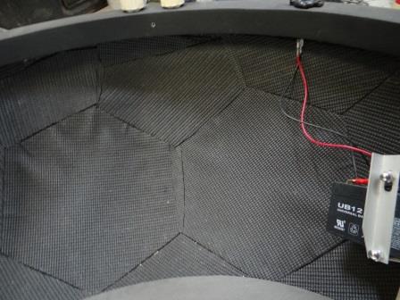
I cut the rug up in hexagon and pentagon shapes, just like a soccer ball (you can find the equations to cut the panels to make a ball shape like this on the internet). The rug had to be fairly thin so it would not apply pressure to the edge of the primary mirror. Indeed there is less than ¼ inch of space between the edge of the primary mirror and the inside of the hemisphere at that location. The bottom of the LTA was now ready to be assembled with the truss tubes and the UTA.
Heating and Ventillation
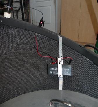
Where I come from, dew and frost are regular guests during observing sessions. They must be dealt with or the observing sessions can be very quickly jeapordized. To deal with this reality, my 20 inch is equipped with anti-dew equipment powered by an onboard 12V rechargeable gel cel battery that nests inside the hemisphere, just above the mirror, but which does not interfere in the light path. I tried to find a way to route a wire to a remote battery or power source, but couldn’t figure out a way to not have the power wire not interfere with the functionning of the telescope.
It turns out, however, that the 2½ pound battery (3.4 amp.hour) ended up also contributing to tube balance, especially around the optical axis. It is placed where it is because that is where it fined tuned tube balance the best. It is fixed on a curved aluminium flat bar (recently installed and not yet painted black) that attaches to the ¾ inch thick aluminium plate imbeded in the resin, under the Mirror. The other end of the flat bar is attached to the hemisphere’s reinforcement ring. It took some experimenting to find the ideal location. When I made the thick plate, under the Mirror, I had anticipated that I might need to attach accessories like counterweights. These attachement points (threaded holes) came in handy for attaching the battery holding bracket.
From it’s position, the battery connects to a 12V cigarette lighter socket attached to the reinforcement ring. The Kendrick temperature controller, located on the UTA, connects through a cable to the cigarette lighter socket. The cable is fixed to one of the two short truss poles, using shrink wrap tubing. I decided against drilling a hole in the bottom and top of the truss pole and feeding the cable through it, because it would have meant drilling a 3/8 inch hole in a 1 inch diameter pole. I was afraid of weakining it. However I may yet change my mind after doing some tests. It would look nicer if the wire was Inside one of the truss tubes.
The four channel Kendrick controller transmits current to heat the 4 inch diagonal, through the spider vanes. It can also simultaneously heat the Rigel finder, the optical finder and the 2 inch eyepiece.
I haven’t installed it yet but I plan on eventually adding a small, removable 4 inch 12V fan which will be attached to the central post that supports the conical mirror. This fan will be used to blow away the turbulent boundary air layer that continuously generates over the surface of the glass as the night air temperature drops. Due to the conical mirrors very thin edge (½”) most of the light gatering surface cools very quickly in a natural fashion. The part of the glass that cools the slowest, the center, will be directly exposed to the centrally located fan. Others have suspended fans in the diagonal shadow before. Should work out well and, with this setup I don’t have to add another set of vanes crossing the light path.
Protective Mirror Shield
The mirror cover is a 1/8 inch thick, 21 inch diameter aluminium plate.
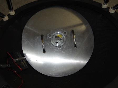
It attaches to the conical mirrors’ central support and has two handles for convenient manipulation. This cover is a real shield, protecting the precious mirror from falling objects and dust when the instrument is not in use. It is so robust it could handle the drop of a large wrench, while keeping the mirror out of harm’s way. I’m also aware of the danger of the battery being so close to the surface of the glass. I want something to protect the mirror, particularly since the battery is recharged in place !
The mirror cover stands about ¼ inch above the edge of the glass. In the center there is a large, knurled aluminium threaded ring that screws onto the protruding threads of the central post that holds the mirror. That attachement ring is held captive by three bolts and large washers that allow the ring to be turned, for screwing/unscrewing, but cannot separate or fall on the mirror when lifting the cover out of the way.
It’s very functionnal but heavy (wheighs 5 pounds). I never quite know what to do with it after I remove it. I’m still looking for a practical place to store it during observations but I often end up leaving it in the car, so it won’t get dirt or grass on it. Dirt would eventually fall back on the mirror suface at the end of an observing session, when the cover is put back on.